

Question: NOTE: The circuit shown also needs modifications in order for it to work on Tinker Cad Project l-Safe Lock We wish to develop a safe
NOTE: The circuit shown also needs modifications in order for it to work on Tinker Cad
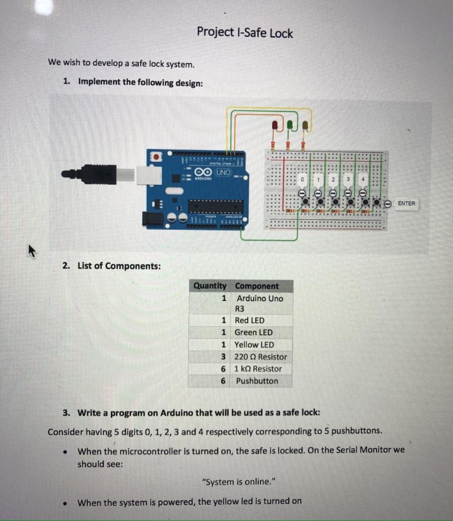
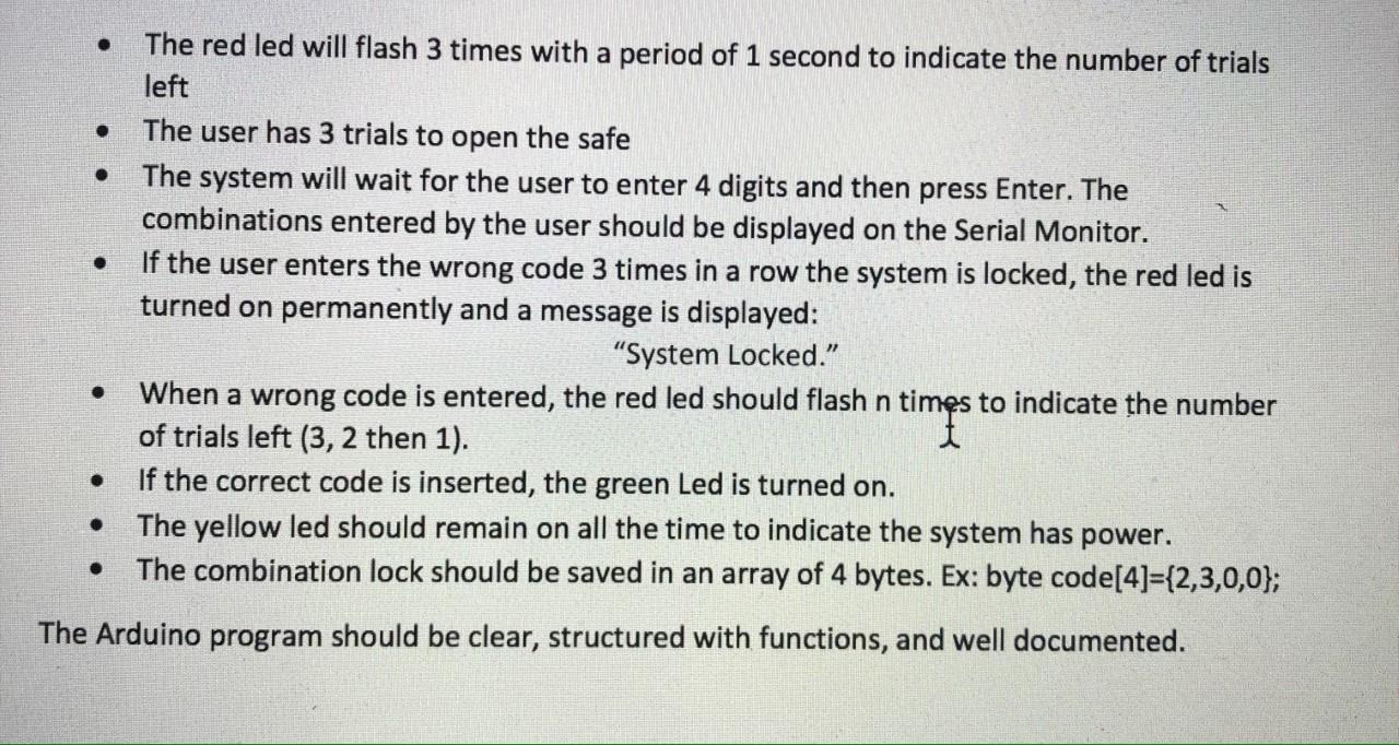
Project l-Safe Lock We wish to develop a safe lock system. 1. Implement the following design: DIGITAL 12:10 OO UNO ARDUINO 1 2 4 0. 0 - a .. ENTER .. ANALOG 2. List of Components: Quantity Component 1 Arduino Uno R3 1 Red LED 1 Green LED 1 Yellow LED 3 220 Resistor 6 1k0 Resistor 6 Pushbutton 3. Write a program on Arduino that will be used as a safe lock: Consider having 5 digits 0, 1, 2, 3 and 4 respectively corresponding to 5 pushbuttons. When the microcontroller is turned on, the safe is locked. On the Serial Monitor we should see: "System is online." When the system is powered, the yellow led is turned on . . The red led will flash 3 times with a period of 1 second to indicate the number of trials left The user has 3 trials to open the safe The system will wait for the user to enter 4 digits and then press Enter. The combinations entered by the user should be displayed on the Serial Monitor. If the user enters the wrong code 3 times in a row the system is locked, the red led is turned on permanently and a message is displayed: "System Locked. When a wrong code is entered, the red led should flash n times to indicate the number of trials left (3, 2 then 1). If the correct code is inserted, the green Led is turned on. The yellow led should remain on all the time to indicate the system has power. The combination lock should be saved in an array of 4 bytes. Ex: byte code[4]={2,3,0,0); . The Arduino program should be clear, structured with functions, and well documented. Project l-Safe Lock We wish to develop a safe lock system. 1. Implement the following design: DIGITAL 12:10 OO UNO ARDUINO 1 2 4 0. 0 - a .. ENTER .. ANALOG 2. List of Components: Quantity Component 1 Arduino Uno R3 1 Red LED 1 Green LED 1 Yellow LED 3 220 Resistor 6 1k0 Resistor 6 Pushbutton 3. Write a program on Arduino that will be used as a safe lock: Consider having 5 digits 0, 1, 2, 3 and 4 respectively corresponding to 5 pushbuttons. When the microcontroller is turned on, the safe is locked. On the Serial Monitor we should see: "System is online." When the system is powered, the yellow led is turned on . . The red led will flash 3 times with a period of 1 second to indicate the number of trials left The user has 3 trials to open the safe The system will wait for the user to enter 4 digits and then press Enter. The combinations entered by the user should be displayed on the Serial Monitor. If the user enters the wrong code 3 times in a row the system is locked, the red led is turned on permanently and a message is displayed: "System Locked. When a wrong code is entered, the red led should flash n times to indicate the number of trials left (3, 2 then 1). If the correct code is inserted, the green Led is turned on. The yellow led should remain on all the time to indicate the system has power. The combination lock should be saved in an array of 4 bytes. Ex: byte code[4]={2,3,0,0); . The Arduino program should be clear, structured with functions, and well documented
Step by Step Solution
There are 3 Steps involved in it

Get step-by-step solutions from verified subject matter experts