

Question: Write Verilog code for the circuit M described below The circuit has four inputs x 1 , x 0 , y 1 , y 0
Write Verilog code for the circuit M described below
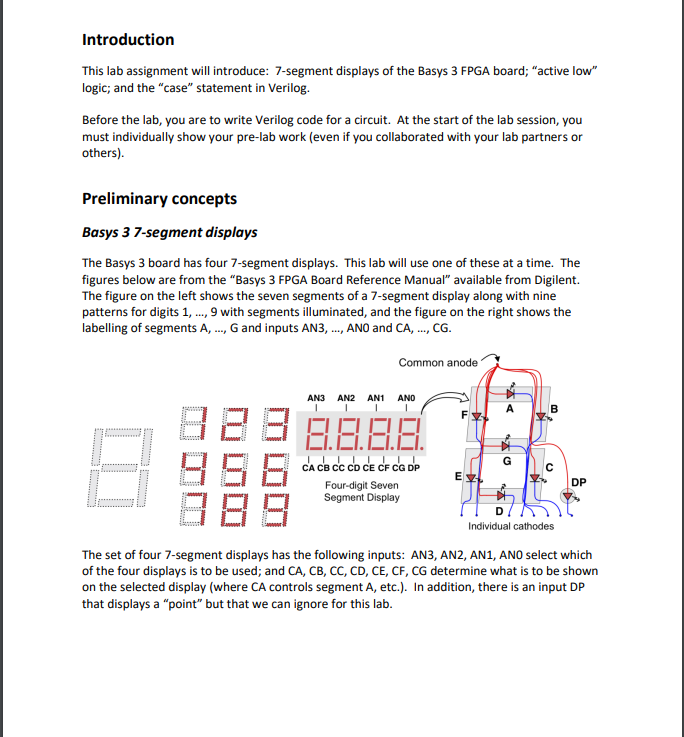
The circuit has four inputs x x y y that can be viewed as two vector inputs X x x and Y y y each with two bits.
Circuit M has output bits grouped into a bit vector A a a a a and a bit vector C c c c c c c c These output bits are going to be connected to the Basys segment display inputs AN AN AN AN and CA CB CC CD CE CF CG respectively in that order
Thus, the circuit that you need to design can be described in terms of what should appear on the Basys board segment displays. Circuit M is part of a setup as shown below. Last screenshot
The two tables below describe the function of circuit M Last screenshot
As example of how M works, suppose X and Y then display should show the number and all other displays should be off.
Step by Step Solution
There are 3 Steps involved in it
1 Expert Approved Answer
Step: 1 Unlock

Question Has Been Solved by an Expert!
Get step-by-step solutions from verified subject matter experts
Step: 2 Unlock
Step: 3 Unlock