

Question: SIM D *11.40 Figure P11.40 shows a series-shunt ampli- fier with a feedback factor 8 = 1. The amplifier is designed so that v
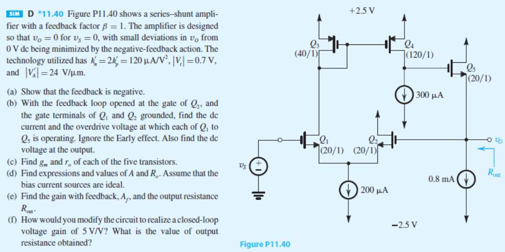
SIM D *11.40 Figure P11.40 shows a series-shunt ampli- fier with a feedback factor 8 = 1. The amplifier is designed so that v = 0 for vs = 0, with small deviations in v, from 0 V dc being minimized by the negative-feedback action. The technology utilized has k=2= 120 A/V, |V|=0.7 V, and V=24 V/m. (a) Show that the feedback is negative. (b) With the feedback loop opened at the gate of Q, and the gate terminals of Q and Q grounded, find the de current and the overdrive voltage at which each of Q, to Qs is operating. Ignore the Early effect. Also find the de voltage at the output. (c) Find g and r, of each of the five transistors. (d) Find expressions and values of A and R. Assume that the bias current sources are ideal. (e) Find the gain with feedback, A,, and the output resistance Rout (f) How would you modify the circuit to realize a closed-loop voltage gain of 5 V/V? What is the value of output resistance obtained? Us Figure P11.40 Q3 (40/1) +2.5 V 2 (20/1) (20/1) 200 A 24 (120/1) 1 ls 300 -2.5 V 0.8 mA (20/1) -0%b Rout
Step by Step Solution
3.40 Rating (156 Votes )
There are 3 Steps involved in it
25vb QI 8201 2115 Then Vor 200A d id 100 A 1 100 Vovi audi WL is KWIL whe... View full answer

Get step-by-step solutions from verified subject matter experts