

Question: You are working for ABC Engineering and have been assigned the task to create a PLC project to control the mixing operation described below. Safety
You are working for ABC Engineering and have been assigned the task to create a PLC project to control the mixing operation described below. Safety is a primary concern for the control system. The system should operate according to the listed parameters.
A position normally open selector switch SS is used to energize the machine. Without turning SS to the ON position, nothing on the system will operate.
While the machine is energized, a green pilot light PL should be on
There is a Start PB Stop PB pushbutton operator station to run a pump motor. The pump motor is controlled by motor starter M Momentarily pressing PB will turn on the pump motor and start filling the tank with water. Momentarily pressing PB will stop the pump motor.
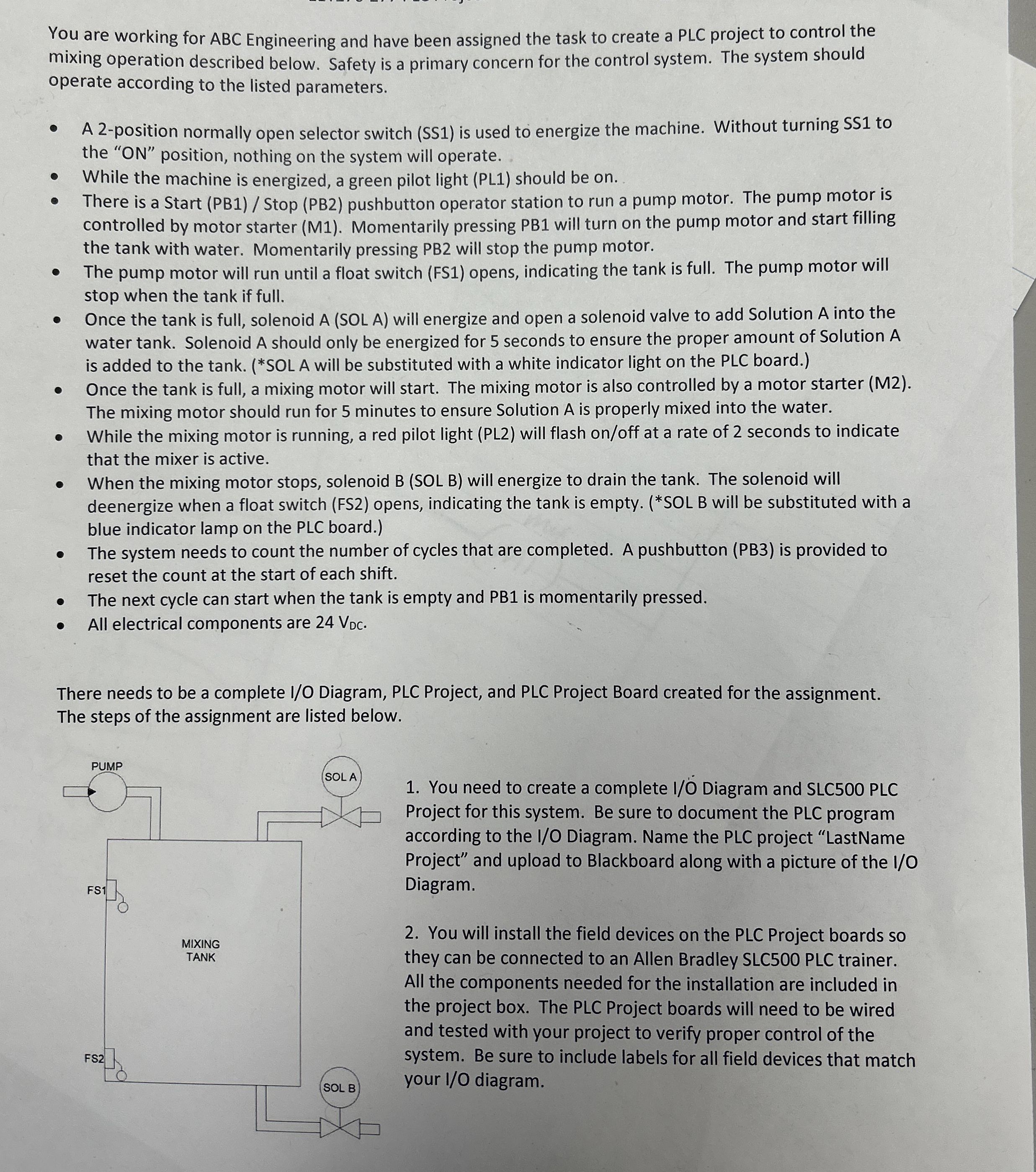
The pump motor will run until a float switch FS opens, indicating the tank is full. The pump motor will stop when the tank if full.
Once the tank is full, solenoid A SOL A will energize and open a solenoid valve to add Solution A into the water tank. Solenoid A should only be energized for seconds to ensure the proper amount of Solution is added to the tank. SOL A will be substituted with a white indicator light on the PLC board.
Once the tank is full, a mixing motor will start. The mixing motor is also controlled by a motor starter M The mixing motor should run for minutes to ensure Solution is properly mixed into the water.
While the mixing motor is running, a red pilot light PL will flash onoff at a rate of seconds to indicate that the mixer is active.
When the mixing motor stops, solenoid B SOL B will energize to drain the tank. The solenoid will deenergize when a float switch FS opens, indicating the tank is empty. SOL B will be substituted with a blue indicator lamp on the PLC board.
The system needs to count the number of cycles that are completed. A pushbutton PB is provided to reset the count at the start of each shift.
The next cycle can start when the tank is empty and PB is momentarily pressed.
All electrical components are
There needs to be a complete IO Diagram, PLC Project, and PLC Project Board created for the assignment. The steps of the assignment are listed below.
You need to create a complete IO Diagram and SLC PLC Project for this system. Be sure to document the PLC program according to the IO Diagram. Name the PLC project "LastName Project" and upload to Blackboard along with a picture of the IO Diagram.
You will install the field devices on the PLC Project boards so they can be connected to an Allen Bradley SLC PLC trainer. All the components needed for the installation are included in the project box. The PLC Project boards will need to be wired and tested with your project to verify proper control of the system. Be sure to include labels for all field devices that match your IO diagram.
Step by Step Solution
There are 3 Steps involved in it
1 Expert Approved Answer
Step: 1 Unlock

Question Has Been Solved by an Expert!
Get step-by-step solutions from verified subject matter experts
Step: 2 Unlock
Step: 3 Unlock