

Question: You must design a cascade compensator to meet the specification for output response to a unit step input, as defined in Table 1. The open
You must design a cascade compensator to meet the specification for output response to a unit step input, as defined in Table 1. The open loop system you should use for your design should be picked from the row appropriate to your surname 1st initial, as should the overshoot and peak time specifications, and all systems should be designed for zero steady state error.
1.Using the root locus method, as defined in Nises Control System Engineering book (module core book): Chapter 9, Example 9.5, design a closed loop system with cascade controller, in Matlab.
I use program which is given by teacher, but the last figure still wrong? I want to know wheres wrong.
This is the program:
%Part B
%For initial 'K'
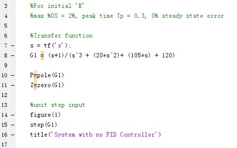
%max %OS = 2%, peak time Tp = 0.3, 0% steady state error
%Transfer function
s = tf('s');
G1 = (s+1)/(s^3 + (20*s^2)+ (105*s) + 120)
P=pole(G1)
Z=zero(G1)
%unit step input
figure(1)
step(G1)
title('System with no PID Controller')
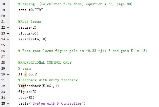
%Damping (Calculated from Nise, equation 4.38, page180)
zeta =0.7797 ;
%Root locus
figure(2)
rlocus(G1)
sgrid(zeta, 0)
% From root locus figure pole is -9.33 +j11.6 and gain K1 = 131
%PROPORTIONAL CONTROL ONLY
% gain
K1 = 65.2
%Feedback with unity feedback
M1=feedback(K1*G1,1)
figure(3)
step(M1)
title('System with P Controller')
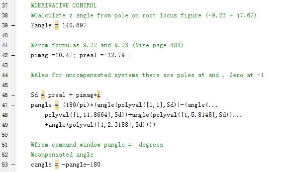
%DERIVATIVE CONTROL
%Calculate z angle from pole on root locus figure (-9.23 + j7.62)
Zangle = 140.697
%From formulas 9.22 and 9.23 (Nise page 484)
pimag =10.47; preal =-12.79 ;
%Also for uncompensated systems there are poles at and . Zero at -1
Sd = preal + pimag*i
pangle = (180/pi)*(angle(polyval([1,1],Sd))-(angle(...
polyval([1,11.8664],Sd))+angle(polyval([1,5.8148],Sd))...
+angle(polyval([1,2.3188],Sd))))
%from command window pangle = degrees
%compensated angle
cangle = -pangle-180
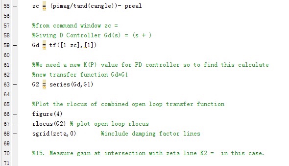
zc = (pimag/tand(cangle))- preal
%from command window zc =
%Giving D Controller Gd(s) = (s + )
Gd = tf([1 zc],[1])
%We need a new K(P) value for PD controller so to find this calculate
%new transfer function Gd*G1
G2 = series(Gd,G1)
%Plot the rlocus of combined open loop transfer function
figure(4)
rlocus(G2) % plot open loop rlocus
sgrid(zeta,0) %include damping factor lines
%15. Measure gain at intersection with zeta line K2 = in this case.
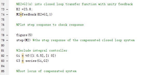
%K2*G2(s) into closed loop transfer function with unity feedback
K2 =23.8;
M2=feedback(K2*G2,1)
%Plot step response to check response
figure(5)
step(M2) %the step response of the compensated closed loop system
%Include integral controller
Gi = tf([1 0.5],[1 0])
G3 = series(Gi,G2)
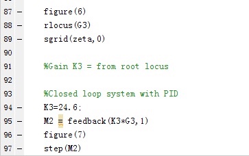
%Root locus of compensated system
figure(6)
rlocus(G3)
sgrid(zeta,0)
%Gain K3 = from root locus
%Closed loop system with PID
K3=24.6;
M2 = feedback(K3*G3,1)
figure(7)
step(M2)
%For initial ,K, %max %OS = 2%, peak time Ip = 0.3, 0% steady state error Iransfer function s = GI 7 tf (' s' ) ; - 8 (s+1 ) / (s^3 + (20*s^2)+ (105*s) + 120) - 10-Ppole (G1) 11ZEzero (G1) 12 13 %unit st ep input 14figure (1) 15step (G1) 16-title( System with no PID Controller)
Step by Step Solution
There are 3 Steps involved in it
1 Expert Approved Answer
Step: 1 Unlock

Question Has Been Solved by an Expert!
Get step-by-step solutions from verified subject matter experts
Step: 2 Unlock
Step: 3 Unlock