

8.4-3. Shown in Fig. P8.4-3 is the block diagram of the temperature control system described in Problem
Question:
8.4-3. Shown in Fig. P8.4-3 is the block diagram of the temperature control system described in Problem 1.6-1. For this problem, ignore the disturbance input. In Fig. P8.4-3 the sensor gain of \(H=0.04\) has been shifted into the forward path to yield a unity feedback system. The stability characteristics are unchanged, since the loop transfer function has not changed. Note that \(c(t)\) is the chamber temperature in degrees Celsius. It is shown in Problem 6.2-4 that with \(T=0.6\), the function \(G(z) H\) is given by
\[
G(z)=(0.04) \frac{z-1}{z} z\left[\frac{2}{s(s+0.5)}ight]=\frac{0.04147}{z-0.7408}
\]
The frequency response for \(G(z)\) is given in Table P8.4-3. The sensor gain \(H=0.04\) is not included in this table.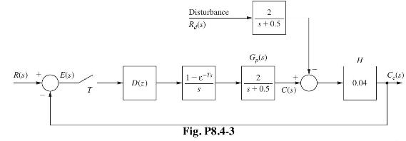
(a) Calculate the dc gains of both the forward path and the closed-loop system, with \(D(z)=1\).
(b) Find the steady-state error \(e_{s s}(k T)\) for a unit step input using (6-19). Express this error in percent.
(c) Let \(D(z)=K\), a pure gain. Find \(\mathrm{K}\) such that the steady-state error in part (b) is 0.05 , or 5 percent. Assume that the resulting system is stable.
(d) It was shown in Problem 7.5-3 that the system is unstable for \(K>41.96\). Can the system in part (c) be implemented to yield a 5 percent steady-state error? Explain your answer.
(e) Design a phase-lag compensator with a de gain of 118.8 to yield a phase margin of \(45^{\circ}\).
(f) What is the percent steady-state error for a constant input for the system in part (e)?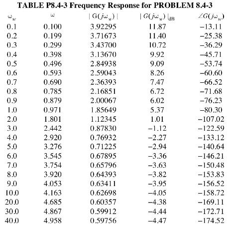
Problem 1.6-1![It is shown in [6] that given the partitioned matrix H DE F G where each partition is nX n, the determinant](https://dsd5zvtm8ll6.cloudfront.net/images/question_images/1705/5/6/6/30465a8e0608f50a1705566303926.jpg)
Problem 6.2-4
Shown in Fig. P6.2-4 is the block diagram of a temperature control system for a large test chamber. This
system is described in Problem 1.6-1. Ignore the disturbance input for this problem.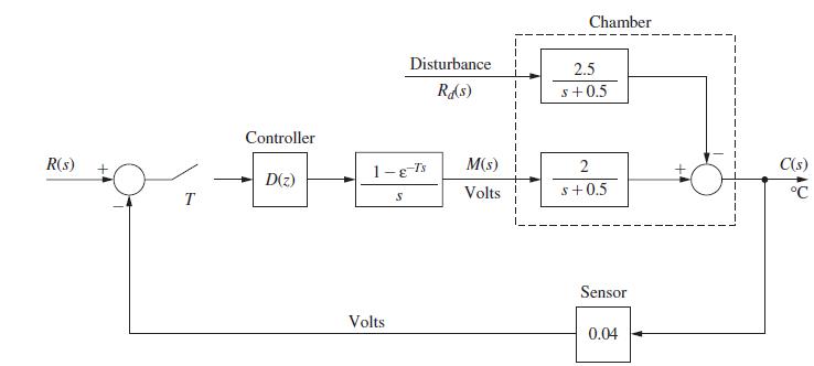
(a) With D(z) = 1 and T = 0.6 s, evaluate and plot the system response if the input is to command a 10C
step in the output. Note that the system input must be a step function with an amplitude of 0.4 V. Why?
(b) Use the results of part (a) to plot the output of the zero-order hold.
(c) Solve for the steady-state output for part (a).
(d) Suppose that the gain of 2 in the plant is replaced with a variable gain K. What value does the output
approach in the steady state as K becomes very large? Assume that the system remains stable as K is
increased (an unrealistic assumption).
Step by Step Answer:
The problem describes a temperature control system and includes several multipart questions related to the systems response and stability Based on the information provided we will address each part on...View the full answer


Digital Control System Analysis And Design
ISBN: 9780132938310
4th Edition
Authors: Charles Phillips, H. Nagle, Aranya Chakrabortty
