

Question: Your group is tasked with performing a brief sustainability analysis of the water-gas shift reaction process presented in Figure 1. The water-gas shift reaction has
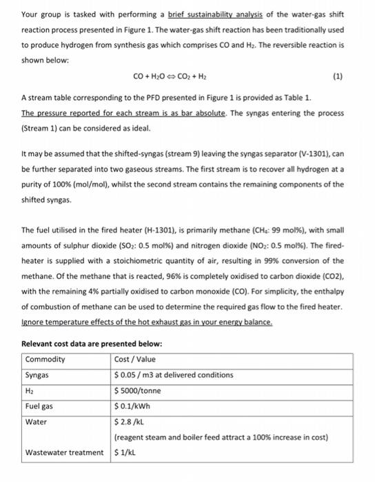
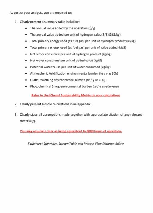
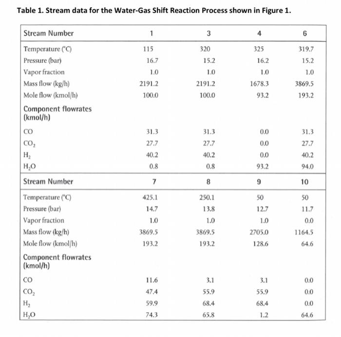
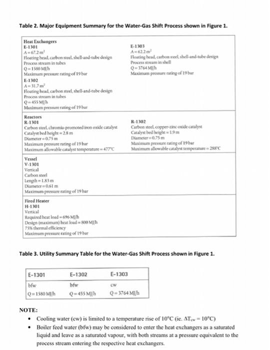
Your group is tasked with performing a brief sustainability analysis of the water-gas shift reaction process presented in Figure 1. The water-gas shift reaction has been traditionally used to produce hydrogen from synthesis gas which comprises co and H2. The reversible reaction is shown below: CO + H2O -> CO2 + H2 (1) A stream table corresponding to the PFD presented in Figure 1 is provided as Table 1. The pressure reported for each stream is as bar absolute. The syngas entering the process (Stream 1) can be considered as ideal. It may be assumed that the shifted-syngas (stream 9) leaving the syngas separator (V-1301),can be further separated into two gaseous streams. The first stream is to recover all hydrogen at a purity of 100% (mol/mol), whilst the second stream contains the remaining components of the shifted syngas. The fuel utilised in the fired heater (H-1301), is primarily methane (CHE: 99 mol%), with small amounts of sulphur dioxide (SO2: 0.5 mol%) and nitrogen dioxide (NO2: 0.5 mol%). The fired- heater is supplied with a stoichiometric quantity of air, resulting in 99% conversion of the methane of the methane that is reacted, 96% is completely oxidised to carbon dioxide (CO2). with the remaining 4% partially oxidised to carbon monoxide (CO). For simplicity, the enthalpy of combustion of methane can be used to determine the required gas flow to the fired heater. Ignore temperature effects of the hot exhaust gas in your energy balance. Relevant cost data are presented below: Commodity Cost/Value Syngas $ 0.05 /m3 at delivered conditions $ 5000/tonne $ 0.1/kWh $ 2.8 /kL (reagent steam and boiler feed attract a 100% increase in cost) Wastewater treatment $ 1/kL H2 Fuel gas Water As part of your analysis, you are required to: 1. Clearly present a summary table including: The annual value added by the operation ($/y) The annual value added per unit of hydrogen sales (5/5) & ($/kg) Total primary energy used (as fuel gas) per unit of hydrogen product (kJ/kg) Total primary energy used (as fuel gas) per unit of value added (kJ/5) Net water consumed per unit of hydrogen product (kg/kg) Net water consumed per unit of added value (kg/5) Potential water reuse per unit of water consumed (ke/kg) Atmospheric Acidification environmental burden (te /y as 50) Global Warming environmental burden (te / yas CO2) Photochemical Smog environmental burden (te / y as ethylene) Refer to the IChemE Sustainability Metrics in your calculations 2. Clearly present sample calculations in an appendix 3. Clearly state all assumptions made together with appropriate citation of any relevant material(s). You may assume a year as being equivalent to 8000 hours of operation. Equipment Summary, Stream Table and Process Flow Diagram follow Table 1. Stream data for the Water-Gas Shift Reaction Process shown in Figure 1. 1 6 115 16.7 4 325 16.2 319.7 15.2 3 320 15.2 10 2191.2 100.0 1.0 1.0 Stream Number Temperature (C) Pressure (bar) Vapor fraction Mass flow (kg/h) Mole flow (kmol/h) Component flowrates (kmol/h) CO CO, H ,0 1.0 2191.2 100.0 1678.3 93.2 3869.5 193.2 0.0 0.0 31.3 27.7 40.2 0.8 31.3 27.7 40.2 0.8 31.3 27.7 40.2 94.0 0.0 93.2 Stream Number 7 8 9 10 Temperature (C) Pressure (bar) Vapor fraction Mass flow (kg/h) Mole flow (kmol/h) Component flowrates (kmol/h) 425.1 14.7 1.0 3869.5 193.2 250.1 13.8 1.0 3869.5 193.2 50 12.7 1.0 2705.0 128.6 50 11.7 0.0 11645 64.6 11.6 47.4 CO2 H H,0 3.1 55.9 68.4 65.8 3.1 55.9 68.4 1.2 0.0 0.0 0.0 64.6 59.9 74.3 Table 2. Major Equipment Summary for the Water-Gas Shift Process shown in Figure 1. E 1303 A622 Floating head, carbon see, sheiland tube design Processinshell Q-3764 Maximum pressure ruting of 19 bar Heat Exchangers E-1301 A67.2m Hosting head carbon steel shell-and-tube design Process stream in tubes Q1580 Mih Maximum pressure rating of 19 bar E-1302 431.7m Hoating head, carbon steel, shell and tube design Process stream in tubes -455M/ Maximum pressure rating of 19 har Reactors R-1301 Carbon steel.chromis promoted iron oxide catalyie Catalyst bed height 28m Diameter -075 m Maximum pressure rating of 19 har Maximum allowable catalyst temperature 477C Vessel V.1301 Vertical Carbon steel Length 183m Diameter 061 m Maximum pressure rating of 19 bur Fired Heater H-1101 Vertical Required heat load -6% Mh Design (maximum) beatload800 MM 75% thermal efficiency Maximum pressure rating of 19 bur R-1302 Carbon steel.copper incide catast Catalyst bed height 19 m Dumeier Maximum presenting of 19 Maximum aliewable catalyst temperature - 2880 Table 3. Utility Summary Table for the Water-Gas Shift Process shown in Figure 1. E-1303 E-1301 bfw Q=1580 Milh E-1302 bfw Q-455 MJ/h cw Q-3764 MI/h NOTE: Cooling water (cw) is limited to a temperature rise of 10C (ie. AT = 10C) Boiler feed water (bfw) may be considered to enter the heat exchangers as a saturated liquid and leave as a saturated vapour, with both streams at a pressure equivalent to the process stream entering the respective heat exchangers
Step by Step Solution
There are 3 Steps involved in it

Get step-by-step solutions from verified subject matter experts