

In the inverting amplifier circuit of Fig. 5-11, v 1 (t) is the input and v 2
Question:
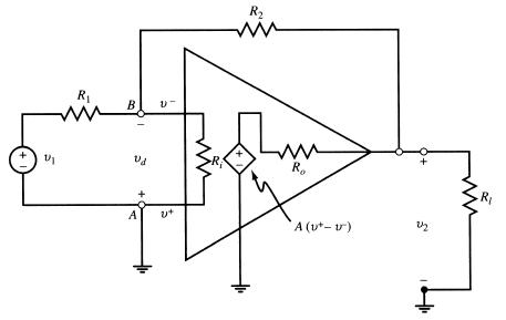
In the inverting amplifier circuit of Fig. 5-11, v1(t) is the input and v2(t) is the output. Let Ri = ∞, Ro = 0, and assume the 741 op amp model specified by Example 5.26.
(a) Find the circuit’s input-output relationship in the time domain.
(b) Let v1 (t) = V cos 2πft produce an output v2(t) = V2 cos (2πft −θ). Develop an expression for magnitude gain |V2/V1|vs. frequency.
Data from Figure 5-11
Data from Example 5.26
At low frequencies the magnitude open-loop gain of a 741 op amp varies as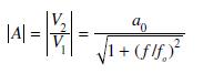
where typically a0 = 200,000 and f0 = 5 Hz.
Fantastic news! We've Found the answer you've been seeking!
Step by Step Answer:
We first find the circuits inputoutput relationship in the time doma...View the full answer

Answered By
GERALD KAMAU
non-plagiarism work, timely work and A++ work
6+ Reviews
11+ Question Solved
Related Book For 
Schaum S Outline Of Electric Circuits
ISBN: 9781260011968
7th Edition
Authors: Mahmood Nahvi, Joseph Edminister
Question Posted:
