All Matches
Solution Library
Expert Answer
Textbooks
Search Textbook questions, tutors and Books
Oops, something went wrong!
Change your search query and then try again
Toggle navigation
FREE Trial
S
Books
FREE
Tutors
Study Help
Expert Questions
Accounting
General Management
Mathematics
Finance
Organizational Behaviour
Law
Physics
Operating System
Management Leadership
Sociology
Programming
Marketing
Database
Computer Network
Economics
Textbooks Solutions
Accounting
Managerial Accounting
Management Leadership
Cost Accounting
Statistics
Business Law
Corporate Finance
Finance
Economics
Auditing
Hire a Tutor
AI Tutor
New
Search
Search
Sign In
Register
study help
engineering
digital design using vhdl a systems approach
Questions and Answers of
Digital Design Using VHDL A Systems Approach
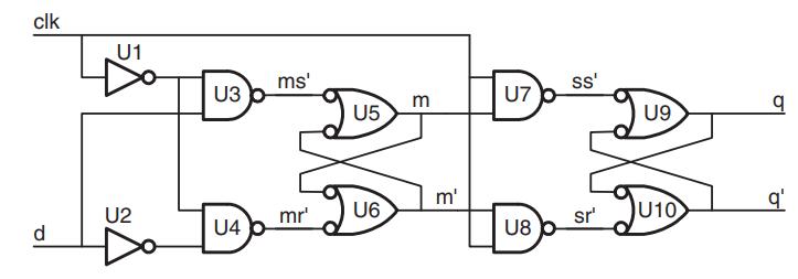
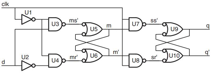
Compute ts for the D flip-flop of Figure 27.8 in terms of the delays of the individual gates. Assume that the delay of gate Ui is ti.Data in Figure 27.8 clk U1 U2 U3 U4 ms' U5 mr'
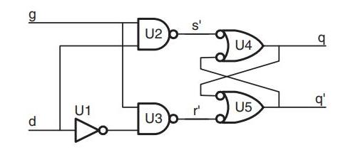
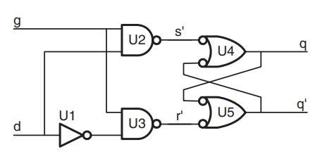
Compute tdDQ for the latch of Figure 27.4 in terms of the delays of the individual gates. Assume that the delay of gate Ui is ti.Data in Figure 27.4 g d U1 U2 U3 s' r' U4 U5 q₁
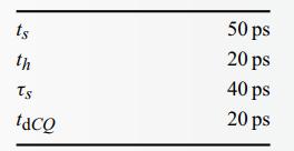
Calculate the mean time to failure of a system with fa = 200 MHz, fcy = 2 GHz, waiting one cycle for synchronization. Use the flip-flop parameters of Table 29.2.Data in Table 29.2. ts th Ts taco 50
Compute ts for the latch of Figure 27.4 in terms of the delays of the individual gates. Assume that the delay of gate Ui is ti.Data in Figure 27.4 g d U1 U2 U3 S' gu U4 U5 q q'
Aside from sensors and games, give three other examples of where always valid timing is used.
Design a VHDL design entity that acts as a receiver for an interface with an eight-bit wide data signal and ready–valid flow control and as a sender for an interface with periodic timing with a
Assume you have a module that consumes 100 units of area and has a delay of 10 ns. The pipeline registers have an area of 2 units, and treg = 500 ps. By varying the number of pipeline stages, make a
Design a once-and-only-once synchronizer. This circuit accepts an asynchronous input a and a clock clk and outputs a signal that goes high for exactly one clock cycle in response to each rising edge
Modify the logic of the FIFO synchronizer to allow the last location to be filled. You will need to add state to encode whether the FIFO is full or empty when head = tail.
Design and code a FIFO synchronizer that uses a presence bit for each register instead of head and tail pointers. When the input writes a value into a register, the corresponding presence bit is
FIFO synchronizer that uses brute-force synchronizers composed of three back-to-back flip-flops to synchronize the head and tail pointers. Assuming the input and output clocks are running at
Go design and implement a digital system that is useful, profitable, interesting, and/or really cool.
Convert 1.109375 to the nearest fixed-point s1.5 representation. Give the absolute and relative errors.
Convert the following floating-point number with a bias of 3 to decimal: 1010E100 in 4E3.
Convert the following floating-point number with a bias of 3 to decimal: 0101E101 in s3E3.
Convert −23 to s3E5 floating-point format with a bias of 8. Give the relative and absolute errors.
Convert 100 000 to s3E5 floating-point format with a bias of 8. Give the relative and absolute errors.
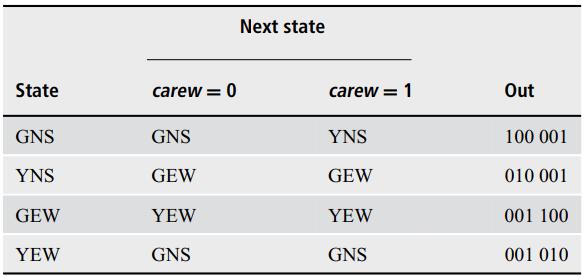
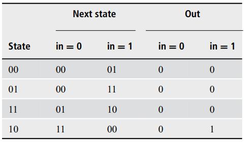
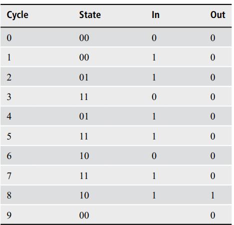
Suppose the traffic-light controller FSM of Table 14.4 did not reset to state GNS. Find a homing sequence for the machine that will get it to state GNS. Data in Table 14.4
Convert 999 to s3E5 floating-point format with a bias of 16. Give the relative and absolute errors.
Calculate the propagation and contamination delays of each input to the output in Figure 15.17. Assume that each gate has a 10 ps delay. Data in Figure 15.17. a b C d Do -8 If
Choose a state assignment for the modified traffic-light controller of Exercise 14.9 and derive the logic to compute the next-state and output values. Show Karnaugh maps for the next-state variables
Write and verify the VHDL that implements your state machine from Exercise 14.9. Data in Exercise 14.9. Modify the traffic-light controller FSM of Table 14.4 so that the FSM stays in state GEW as
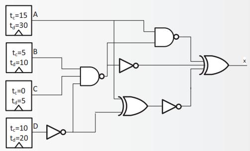
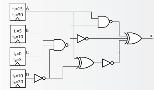
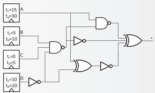
Compute the contamination and propagation delays of the circuit in Figure 15.18 from flip-flop C to the output. Assume that the delay through each gate is 10 ps. Data in Figure 15.18 t₂=15
Compute the contamination and propagation delays of the circuit in Figure 15.18 from flip-flop D to the output. Assume that the delay through each gate is 10 ps. Data in Figure 15.18 t=15
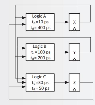
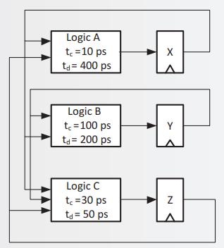
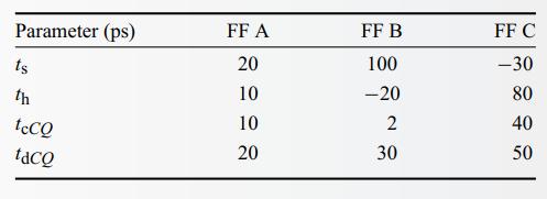
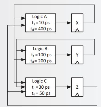
For flip-flop A of Table 15.1 and a 2 GHz clock, check Figure 15.19 for timing violations. If there is a hold violation, indicate where delay must be added, specify the necessary delay, and recheck
For flip-flop B of Table 15.1 and a 2 GHz clock, check Figure 15.19 for timing violations. If there is a hold violation, indicate where delay must be added, specify the necessary delay, and recheck
For flip-flop C of Table 15.1 and a 2 GHz clock, check Figure 15.19 for timing violations. If there is a hold violation, indicate where delay must be added, the necessary delay, specify and recheck
For flip-flop C of Table 15.1 and a 1 GHz clock, for any block of logic that separates two flip-flops, what is the minimum tc and maximum td?Data in Table 15.1 Parameter (ps) ts th tccQ taco FF
Calculate the maximum allowable clock skew in Figure 15.19. Indicate between which pair of flip-flops the skew occurs and whether it will trigger a setup or hold violation. Use flip-flop
Repeat Exercise 15.22, instead using flip-flop specification B and a 2 ns clock. Data in Exercise 15.22,Calculate the maximum allowable clock skew in Figure 15.19. Indicate between which pair of
Multiplying two 64-bit numbers gives a 128-bit result. (a) Assuming the inputs and outputs are terminated by flip-flops, how many combinations of start and end flip-flops exist in the system?(b)
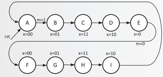
Consider the state diagram shown in Figure 17.18. Data in Figure 17.18.(a) Identify identical or nearly identical sequences of states in this FSM. (b) Draw the state diagram for a separate
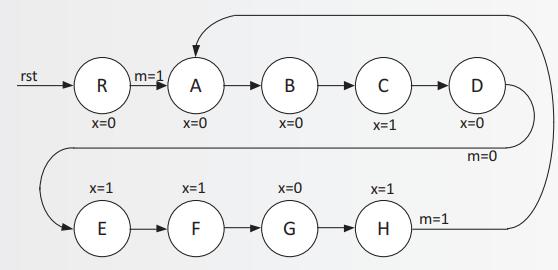
Consider the state diagram shown in Figure 17.17.Data in Figure 17.17.(a) Identify identical or nearly identical sequences of states in this FSM. (b) Draw the state diagram for a separate FSM
Write the VHDL for your saturating counter of Exercise 16.4. Data in Exercise 16.4.Draw the block diagram for a counter that can count up, count down, and load. This counter, however, must
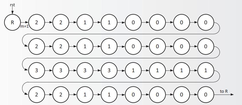
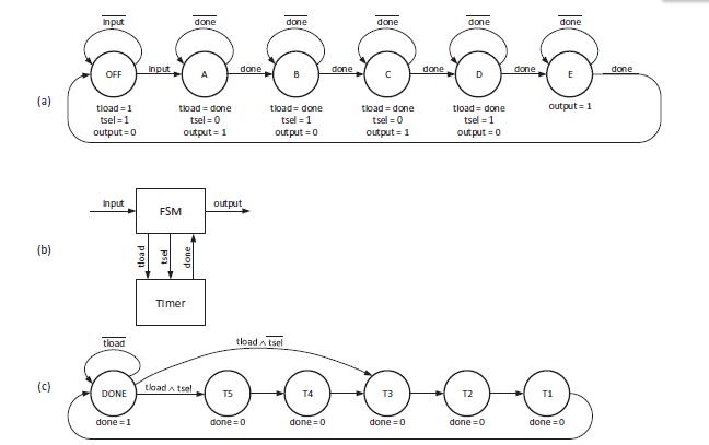
Consider the state diagram shown in Figure 17.19.Data in Figure 17.19.(a) Identify identical or nearly identical sequences of states in this FSM that can be replaced with a timer. (b) Draw a
Modify your SOS flasher from Exercises 17.11 and 17.12 to implement an FSM to flash the Morse code for TOSS instead of SOS. (The code for T is a single long flash.) Data in Exercises 17.11Modify
Write and verify the VHDL for the SOS flasher (datapath + microcoded FSM) of Exercise 18.7. Data in Exercise 18.7. Modify the microcoded FSM and microcode from Section 18.1 and Exercise 18.6 to act
Modify the sequencer to include a counter that indicates in position in the string of the character currently being matched. Update both the block diagram and VHDL to implement the counter.
Write and verify the VHDL for a controller that supports call/return instructions.
Describe a controller that is able to make calls and returns up to three levels deep. This allows subroutines to call subroutines (that call subroutines).
Alter the modified SOS machine from Exercise 19.4 further so that the pauses between dots and dashes within a character may be one or two consecutive 0s, the spaces between characters are three or
Build a module that instantiates eight different tic-tac-toe modules and plays them against each other in a single-elimination tournament. Each match should be best of two, alternating the module
Write a feature list for a digital watch chip.
In the DES specification and block diagram, add an input interrupt that stops DES computation. Be sure to specify the values of the outputs on interrupt, the state the system goes into, and what
At the end of DES cracking, we would like to output the plaintext data. Specify this feature and include it in the partitioned block diagram.
Give a specification and partitioning of a string searcher. Given three different sequences to find and a single long string to search, your block should output the number of occurrences of each
Specify and partition an elevator controller. You should take floor requests as inputs and output the door state (open or closed), destination floor, and a signal to start the elevator moving.
Aside from what was mentioned in the text, give three examples of where periodically valid timing is used.
Aside from what was mentioned in the text, give three examples of where timing with flow control is used.
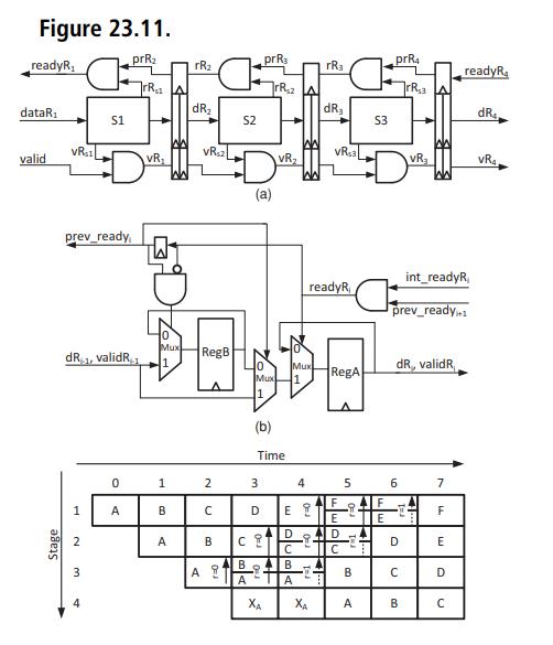
Repeat Exercise 23.11 with the double buffer of Figure 23.11 and the VHDL of Figure 23.12. The fail signal should propagate by only one stage per cycle (like the ready signal).Data in Exercise
Design a VHDL design entity for receiving periodic (N = 10) eight-bit signals and outputting them to a ready–valid interface. Your module should include the ability to save up to two of the
Describe three different situations that can insert unpredictability into a system with an isochronous timed output. For each reason, explain how you could bound the worst case error.
Design a VHDL design entity that receives a serialized signal over eight cycles using frame-level flow control and acts as a sender for a serialized signal over eight cycles using cycle-level flow
Design a 4 × 4 crossbar that supports multicast messaging. Each input can request one or more outputs, but arbitration must be done as all or nothing. That is, an input is either granted to
For each of the following memories, state how many bits are needed in order to address the full capacity. Also explain which bits are used for byte selection, bank selection, and word selection.
Compute th for the D flip-flop of Figure 27.8 in terms of the delays of the individual gates. Assume that the delay of gate Ui is ti.Data in Figure 27.8
Using the minimum number of addresses, describe an access pattern that never hits in each of the following caches: (a) A direct-mapped cache with n different sets; (b) A fully associative
Modify the edge circuit of Exercise 26.4 to alternate edges between three outputs. Data in Exercise 26.4 The toggle circuit of Section 26.2 is a pulse toggle – a circuit in which alternate
Compute tdCQ for the D flip-flop of Figure 27.8 in terms of the delays of the individual gates. Assume that the delay of gate Ui is ti.Data in Figure 27.8 clk d U1 U2 U3 U4 ms' U5 mr'
Write a flow table for the toggle circuit, but this time creating a new state for each of the first eight transitions on in. Then determine which states are equivalent, in order to reduce your flow
With a target of having only one illegal asynchronous transition every 0.01 s, compute the maximum fa in a system where ts = th = 20 ps and fcy = 4 GHz.
You are a designer tasked with implementing a flip-flop that, in a skew-free environment, eliminates all hold violations. Write an inequality that must be true about your flip-flop in order to avoid
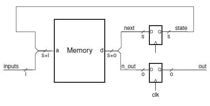
Consider a datapath FSM with a four-bit state register state whose nextstate function is described by the following VHDL statement:nxt <= "000" when rst = ’1’ else (state(2 downto 0) & not
Consider a datapath FSM with a four-bit state register state whose next-state function is described by the following VHDL statement: nxt <= "0001" when rst = ’1’ else (state(2 downto 0)
Consider a datapath FSM with a five-bit state register state whose next-state function is described by the following VHDL statement: nxt <= "00001" when rst = ’1’ else (state(3 downto 0)
Draw the block diagram for a counter that can count up, count down, and load. This counter, however, must saturate when counting up (at a programmable maximum count) and counting down (at zero).
Draw the block diagram for a datapath circuit to compute 16-bit Fibonacci numbers. During each cycle, the circuit should output the next Fibonacci number (starting with 0 after reset). The circuit
How many bits in your code from Exercise 18.1 must you change in order for a light to change direction only when no cars are coming in the current direction and there is a car in the opposite
Write a VHDL testbench that applies six directed test patterns to a 32-bit 2’s complement adder. Explain what each of your patterns is checking for.
Add the ability to stop and pause playback of a song. Discuss where playback should begin when the user again asserts the start signal.
In the music player specification and simple block diagram, add the ability to input a song file into the RAM.
Convert the following fixed-point number to decimal: 1.0101 in 1.4.
The finite-state machine described by Table 14.2 does not have a reset input. Explain how you can get the machine in a known state regardless of its initial starting state by providing a fixed input
Write and verify the VHDL that implements your state machine from Exercise 14.3.Data in Exercise 14.3.
Compute the contamination and propagation delays of the circuit in Figure 15.18 from flip-flop A to the output. Assume that the delay through each gate is 10 ps.Data in Figure 15.18 t=15 A t=30 t=5
Compute the contamination and propagation delays of the circuit in Figure 15.18 from flip-flop B to the output. Assume that the delay through each gate is 10 ps. Data in Figure 15.18 t=15
You need to represent a relative pressure signal with a range from −10 PSI to 10 PSI with an accuracy of 0.1 PSI. Select a fixed-point representation that covers this range with the specified
For flip-flop A in Table 15.1, draw a waveform showing the flip-flop’s input going high just before ts and low just after th. Include clk, D, and Q (previously 0). Label all constraints on your
Convert the following floating-point number with a biasof 3 to decimal: 1111E111 in 4E3.
For flip-flop B in Table 15.1, draw a waveform showing the flip-flop’s input going high just before ts and low just after th. Include clk, D, and Q (previously 0). Label all constraints on your
For flip-flop C in Table 15.1, draw a waveform showing the flipflop’s input going high just before ts and low just after th. Include clk, D, and Q (previously 0). Label all constraints on your
After taping out a chip, it comes back from the fabrication plant and does not work. How can you test whether the failure is either a setup violation or a hold violation? Describe the tests to run.
Select a fixed-point representation that covers a range from 0.001 to 1 with an accuracy of 1% across the range and uses a minimum number of bits.
Convert −1.171875 to the nearest fixed-point s1.5 representation. Give the absolute and relative errors.
Convert 0.3775 to the nearest fixed-point s1.5 representation. Give the absolute and relative errors.
Convert 1.5999 to the nearest fixed-point s1.5 representation. Give the absolute and relative errors.
Convert the following fixed-point number to decimal: 101.011 in s2.3.
Convert the following fixed-point number to decimal: 101.011 in 3.3.
Convert the following fixed-point number to decimal: 11.0101 in s1.4.
Convert 1963 from decimal to binary notation. Use the minimum number of bits possible. Also express the result in hexadecimal.
Code your design from Exercise 9.12 in VHDL and verify it with selected test cases.Data in Exercise 9.12The priority arbiter of Section 9.3 currently breaks ties in favor of the lower-numbered input.
Convert 817 from decimal to binary notation. Use the minimum number of bits possible. Express the result in hexadecimal.
Convert 1492 from decimal to binary notation. Use the minimum number of bits possible. Express the result in hexadecimal.
Convert 2012 from decimal to binary notation. Use the minimum number of bits possible. Also express the result in hexadecimal.
Convert 0011 0011 0001 from binary to decimal notation.
Convert 0111 1111 from binary to decimal notation.
Convert 0100 1100 1011 0010 1111 from binary to decimal notation.
Convert 0001 0110 1101 from binary to decimal notation.
Convert 2C from hexadecimal to decimal notation. Also express the number in binary-coded decimal (BCD) notation.
Convert BEEF number from hexadecimal to decimal notation. Also express the number in binary-coded decimal (BCD) notation.
Showing 1 - 100
of 216
1
2
3