

Question: Draw topographic profiles and structure sections AA and BB on the Bree Creek Quadrangle map. Draw them as neatly and accurately as possible, and color
Draw topographic profiles and structure sections A–A’ and B–B’ on the Bree Creek Quadrangle map. Draw them as neatly and accurately as possible, and color each unit on the structure sections as it is colored on your map. Because the map shows that the Tertiary section rests on a Cretaceous crystalline basement, you must show the crystalline basement beneath the Tertiary rocks on your structure section. These structure sections will later become part of your synthesis of the structural history of the Bree Creek Quadrangle.
Use your thickness measurements from Problems 3.2 and 3.3. Units should maintain a constant thickness in your structure section unless you have evidence to the contrary.
Remember that structure sections involve a great deal of interpretation and that, until someone drills a hole, there is no single correct answer. But your structure section must make sense and be compatible with the geology shown on the map. As in all scientific interpretations, the best solution is the simplest one that is compatible with the available data.
In the northeastern part of themap area, someone did drill holes. Problem 2.2 (Fig. G-3) involved the drawing of a structure contour map on the upper surface of the Bree Conglomerate. Use your completed structure contour map to determine the depth of the Bree Conglomerate in the eastern half of structure section A–A’.
Be sure that your structure sections have all of the 10 features listed above.
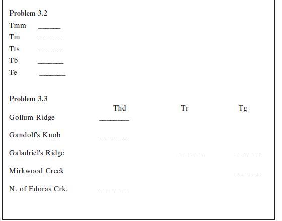
Problems 3.2
The Paleogene (Paleocene through Oligocene) units of the Bree Creek Quadrangle were folded and then eroded nearly flat. Determine the approximate stratigraphic thickness of each of these Paleogene units.
To do this, for each unit find a place that is not in the hinge zone of a fold, where the topography is nearly flat, where both the upper and lower contacts are exposed, and where the dip is fairly constant. The horizontal distance h must be measured perpendicular to the strike. A good place to measure the Bree Conglomerate, for example, is where Galadriel’s Creek crosses it in the southwestern corner of the map. In places where the dip is not completely consistent you may have to use an average dip. (Because of the large contour interval on this map and the absence of completely flat terrain, thickness determinations will be somewhat variable.)
Tmm _____ (NE corner at 1600-ft contour)
Tm _____ (W of Galadriel’s Ridge at 36°W dip)
Tts _____ (NE corner at 2000- and 2400-ft contours)
Tb _____ (at Galadriel’s Creek)
Te _____

Problems 3.3
Determine the approximate thickness of the Neogene units in the areas indicated. (Both the Helm’s Deep Sandstone and the Rohan Tuff have quite variable thicknesses. The Rohan Tuff was tilted and partly eroded prior to the deposition of the Helm’s Deep Sandstone, and the Helm’s Deep Sandstone has no upper contact. Where appropriate, determine the range of thicknesses.)

Problem 2.2
Draw structure contours on Fig. G-3. Use a 400-ft contour interval (including 0, 400, 800, 1200, etc.). Assume that, unlike the example in Fig. 2.8, this surface is not broken by faults, so your structure contours should be continuous.
If you do not know how to begin, here is a suggestion. Find a point, such as the 799-ft point, with an elevation that is close to the elevation of one of the contour lines. You know that the 800-ft contour passes very close to this point, but where does it go from there? To the east and northeast are two points with elevations of 1013 ft and 516 ft; 800 lies between these two elevations, so the 800-ft contour must pass between these two points, closer to the 1013-ft point than to the 516-ft point. Once you have a few lines drawn, the rest will fall into place. Your structure contours should be smooth, subparallel lines. Use a pencil; this is a trial-and-error operation. Be sure to label the elevation of each structure contour as you draw it.
When you are finished you should be able to recognize some folds. Using the symbols in Appendix F, draw appropriate fold symbols on your structure-contour map. Also draw a few strike-and-dip symbols on the map, but without specifying the amount of dip.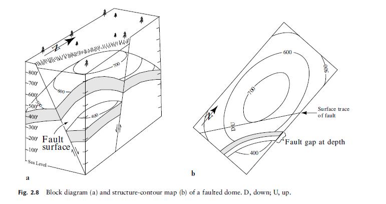
Fig. G-3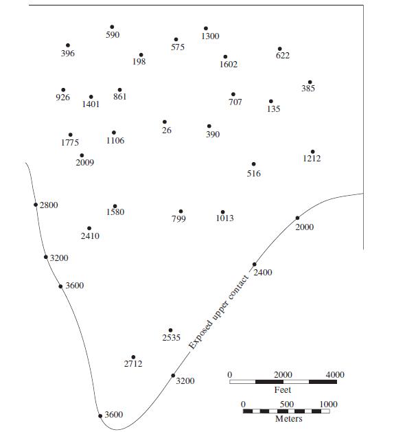
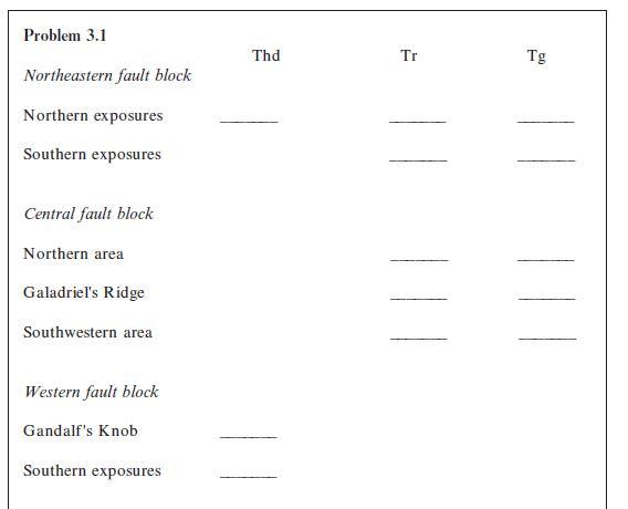
Problem 3.1 Northeastern fault block Northern exposures Southern exposures Central fault block Northern area Galadriel's Ridge Southwestern area Western fault block Gandalf's Knob Southern exposures Thd Tr Tg
Step by Step Solution
3.43 Rating (159 Votes )
There are 3 Steps involved in it
To create the topographic profiles and structure sections for AA and BB on the Bree Creek Quadrangle map follow these steps Step 1 Prepare Your Map an... View full answer

Get step-by-step solutions from verified subject matter experts