

Question: A class-A emitter follower biased with a constant current source is shown in Figure P8.16. Assume circuit parameters of (V^{+}=12 mathrm{~V}, V^{-}=-12 mathrm{~V}), and (R_{L}=20
A class-A emitter follower biased with a constant current source is shown in Figure P8.16. Assume circuit parameters of \(V^{+}=12 \mathrm{~V}, V^{-}=-12 \mathrm{~V}\), and \(R_{L}=20 \Omega\). The transistor parameters are \(\beta=40\) and \(V_{B E}(\mathrm{on})=0.7 \mathrm{~V}\). The minimum current in \(Q_{1}\) is to be \(i_{E 1}=50 \mathrm{~mA}\) and the minimum collectoremitter voltage is to be \(v_{C E}(\min )=0.7 \mathrm{~V}\).
(a) Determine the value of \(R\) that will produce the maximum possible output voltage swing. What is the value of \(I_{Q}\) ? What are the maximum and minimum values of \(i_{E 1}\) ?
(b) Using the results of part (a), calculate the conversion efficiency.
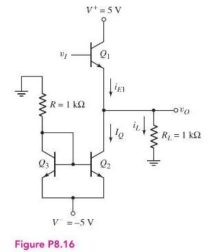
V+= 5 V Q1 R=1 kQ El Q3 Q2 V =-5V Figure P8.16 R = 1 k
Step by Step Solution
There are 3 Steps involved in it

Get step-by-step solutions from verified subject matter experts