

Question: (a) Derive the voltage transfer function (T(s)=V_{o}(s) / V_{i}(s)) for the circuit shown in Figure 7.10, taking both capacitors into account. (b) Let (R_{S}=R_{P}=10 mathrm{k}
(a) Derive the voltage transfer function \(T(s)=V_{o}(s) / V_{i}(s)\) for the circuit shown in Figure 7.10, taking both capacitors into account.
(b) Let \(R_{S}=R_{P}=10 \mathrm{k} \Omega, C_{S}=1 \mu \mathrm{F}\), and \(C_{P}=10 \mathrm{pF}\). Calculate the actual magnitude of the transfer function at \(f_{L}=1 /\left[(2 \pi)\left(R_{S}+R_{P}\right) C_{S}\right]\) and at \(f_{H}=1 /\left[(2 \pi)\left(R_{S} \| R_{P}\right) C_{P}\right]\). How do these magnitudes compare to the maximum magnitude of \(R_{P} /\left(R_{S}+R_{P}\right)\) ?
(c) Repeat part (b) for \(R_{S}=\) \(R_{P}=10 \mathrm{k} \Omega\) and \(C_{S}=C_{P}=0.1 \mu \mathrm{F}\).
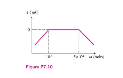
T(jw) 5 102 5x10⁴ (rad/s) Figure P7.10
Step by Step Solution
3.44 Rating (163 Votes )
There are 3 Steps involved in it

Get step-by-step solutions from verified subject matter experts