

Consider the circuits shown in Figure P2.35. Each diode cut-in voltage is (V_{gamma}=0.7 mathrm{~V}). (a) Plot (v_{O})
Question:
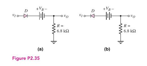
Consider the circuits shown in Figure P2.35. Each diode cut-in voltage is \(V_{\gamma}=0.7 \mathrm{~V}\).
(a) Plot \(v_{O}\) versus \(v_{I}\) over the range \(-10 \leq v_{I} \leq+10 \mathrm{~V}\) for the circuit in Figure P2.35 (a) for (i) \(V_{B}=5 \mathrm{~V}\) and (ii) \(V_{B}=-5 \mathrm{~V}\).
(b) Repeat part (a) for the circuit in Figure P2.35(b).
Fantastic news! We've Found the answer you've been seeking!
Step by Step Answer:

Answered By
Vincent Omondi
I am an extremely self-motivated person who firmly believes in his abilities. With high sensitivity to task and operating parameters, deadlines and keen on instructions, I deliver the best quality work for my clients. I handle tasks ranging from assignments to projects.
109+ Reviews
314+ Question Solved
Related Book For 

Microelectronics Circuit Analysis And Design
ISBN: 9780071289474
4th Edition
Authors: Donald A. Neamen
Question Posted:
