

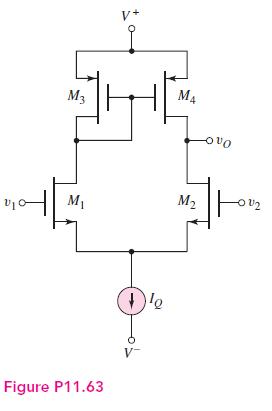
Consider the diff-amp that was shown in Figure P11.63. The circuit and transistor parameters are (V^{+}=2.8 mathrm{~V},
Question:
Consider the diff-amp that was shown in Figure P11.63. The circuit and transistor parameters are \(V^{+}=2.8 \mathrm{~V}, V^{-}=-2.8 \mathrm{~V}, I_{Q}=120 \mu \mathrm{A}\), \(K_{n}=K_{p}=0.2 \mathrm{~mA} / \mathrm{V}^{2}, V_{T N}=+0.3 \mathrm{~V}, V_{T P}=-0.3 \mathrm{~V}\), and \(\lambda_{n}=\lambda_{p}=\) \(0.025 \mathrm{~V}^{-1}\).
(a) Determine the differential-mode voltage gain.
(b) What is the output resistance of the diff-amp?
(c) What is the maximum commonmode voltage that may be applied?
Fantastic news! We've Found the answer you've been seeking!
Step by Step Answer:

Answered By
Navdeep Singh
? I have good understanding of data structure, designing of algorithms, designing and optimization of SQL database .
? I have hands-on experience in machine learning, computer vision.
? I like to do competitive programming in java.
? I have done B.tech in Computer Science Engineering and completed courses in deeplearning.ai, Advanced data structure in java from coursera. I have a strong aptitude for solving problems based on computer science and mathematics upto graduate level.
? I am a freelancer worked on Machine learning model in which I used convolutional and recurrent neural network to get caption or description of image input with 90% accuracy on test data-set. I also did project based on google map API in which i used BFS, Dijkstra, a* algorithm to find shortest possible route between two location on a map.
? I've good understanding of CCM using quadient designer, interactive, automation, scalar. I worked on these softwares during freelancing, created workflow diagrams and process jobs in it to create interactive documents of various formats according to customer needs and requirements.
? Also, I have built MERN stack web application and flutter app for android with CI/CD mindset, sometimes used firebase according to client specification.
0 Reviews
10+ Question Solved
Related Book For 

Microelectronics Circuit Analysis And Design
ISBN: 9780071289474
4th Edition
Authors: Donald A. Neamen
Question Posted:
