

The bias voltages in the diff-amp shown in Figure P11.31 are changed to (V^{+}=3 mathrm{~V}) and (V^{-}=-3
Question:
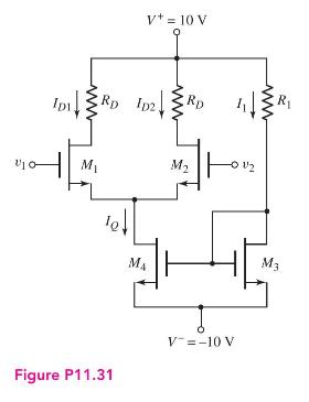
The bias voltages in the diff-amp shown in Figure P11.31 are changed to \(V^{+}=3 \mathrm{~V}\) and \(V^{-}=-3 \mathrm{~V}\). The transistor parameters are \(K_{n 1}=K_{n 2}=\) \(100 \mu \mathrm{A} / \mathrm{V}^{2}, K_{n 3}=K_{n 4}=200 \mu \mathrm{A} / \mathrm{V}^{2}, \lambda_{1}=\lambda_{2}=0, \lambda_{3}=\lambda_{4}=0.01 \mathrm{~V}^{-1}\) and \(V_{T N}=0.3 \mathrm{~V}\) (all transistors).
(a) Design the circuit such that \(V_{D S 1}=V_{D S 2}=4 \mathrm{~V}\) and \(I_{D 1}=I_{D 2}=60 \mu \mathrm{A}\) when \(v_{1}=v_{2}=-1.15 \mathrm{~V}\). (i) What are the values of \(I_{Q}\) and \(I_{1}\) ? (ii) What are the values of \(R_{D}\) and \(R_{1}\) ? (iii) What are the values of \(V_{G S 1}\) and \(V_{G S 4}\) ?
(b) Calculate the change in \(I_{Q}\) if \(v_{1}=v_{2}=+1.15 \mathrm{~V}\).
Step by Step Answer:


Microelectronics Circuit Analysis And Design
ISBN: 9780071289474
4th Edition
Authors: Donald A. Neamen
