

The circuit in Figure P9.65 is a representation of the common-mode and differential-input signals to a difference
Question:
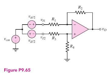
The circuit in Figure P9.65 is a representation of the common-mode and differential-input signals to a difference amplifier. The output voltage can be written as
\[v_{O}=A_{d} v_{d}+A_{c m} v_{c m}\]
where \(A_{d}\) is the differential-mode gain and \(A_{c m}\) is the common-mode gain.
(a) Setting \(v_{d}=0\), show that the common-mode gain is given by
\[A_{c m}=\frac{\left(\frac{R_{4}}{R_{3}}-\frac{R_{2}}{R_{1}}\right)}{\left(1+R_{4} / R_{3}\right)}\]
(b) Determine \(A_{\text {cm }}\) if \(R_{1}=10.4 \mathrm{k} \Omega, R_{2}=62.4 \mathrm{k} \Omega, R_{3}=9.6 \mathrm{k} \Omega\), and \(R_{4}=86.4 \mathrm{k} \Omega\).
(c) Determine the maximum value of \(\left|A_{c m}\right|\) if \(R_{1}=\) \(20 \mathrm{k} \Omega \pm 1 \%, R_{2}=80 \mathrm{k} \Omega \pm 1 \%, R_{3}=20 \mathrm{k} \Omega \pm 1 \%\), and \(R_{4}=80 \mathrm{k} \Omega \pm 1 \%\).
Step by Step Answer:


Microelectronics Circuit Analysis And Design
ISBN: 9780071289474
4th Edition
Authors: Donald A. Neamen
