

The circuit parameters of the diff-amp shown in Figure 11.2 are (V^{+}=3 mathrm{~V}, V^{-}=-3 mathrm{~V}), and (I_{Q}=0.25
Question:
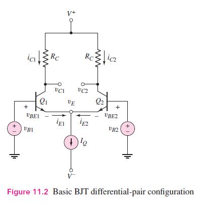
The circuit parameters of the diff-amp shown in Figure 11.2 are \(V^{+}=3 \mathrm{~V}, V^{-}=-3 \mathrm{~V}\), and \(I_{Q}=0.25 \mathrm{~mA}\). Base currents are negligible and \(V_{A}=\infty\) for each transistor.
(a) Design the circuit such that a differential-mode output voltage of \(v_{o}=v_{C 1}-v_{C 2}=1.2 \mathrm{~V}\) is produced when a differential-mode input voltage of \(v_{d}=v_{1}-v_{2}=16 \mathrm{mV}\) is applied.
(b) What is the maximum possible common-mode input voltage that can be applied such that the input transistors remain biased in the forward-active mode?
(c) For a one-sided output, what is the value of \(\mathrm{CMRR}_{\mathrm{dB}}\) if the output resistance of the current source is \(R_{o}=4 \mathrm{M} \Omega\) ?
Figure 11.2:-
Step by Step Answer:


Microelectronics Circuit Analysis And Design
ISBN: 9780071289474
4th Edition
Authors: Donald A. Neamen
