

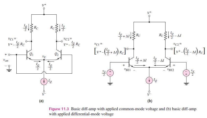
The diff-amp in Figure 11.3 of the text has parameters (V^{+}=+5 mathrm{~V}), (V^{-}=-5 mathrm{~V}, R_{C}=8 mathrm{k} Omega),
Question:
The diff-amp in Figure 11.3 of the text has parameters \(V^{+}=+5 \mathrm{~V}\), \(V^{-}=-5 \mathrm{~V}, R_{C}=8 \mathrm{k} \Omega\), and \(I_{Q}=0.5 \mathrm{~mA}\). The transistor parameters are \(\beta=120, V_{B E}\) (on) \(=0.7 \mathrm{~V}\), and \(V_{A}=\infty\).
(a) Using Figure 11.3(a), determine the maximum common-mode input voltage \(v_{c m}\) that can be applied such that the transistors \(Q_{1}\) and \(Q_{2}\) remain biased in the active region.
(b) Using Figure 11.3(b), determine the change in \(v_{C 2}\) from its dc value if \(v_{d}=18 \mathrm{mV}\).
(c) Repeat part (b) if \(v_{d}=10 \mathrm{mV}\).
Figure 11.3:-
Fantastic news! We've Found the answer you've been seeking!
Step by Step Answer:

Answered By
Aun Ali
I am an Associate Member of Cost and Management Accountants of Pakistan with vast experience in the field of accounting and finance, including more than 17 years of teaching experience at university level. I have been teaching at both undergraduate and post graduate levels. My area of specialization is cost and management accounting but I have taught various subjects related to accounting and finance.
13+ Reviews
32+ Question Solved
Related Book For 

Microelectronics Circuit Analysis And Design
ISBN: 9780071289474
4th Edition
Authors: Donald A. Neamen
Question Posted:
