

For the transistors in the circuit in Figure P11.5, the parameters are (beta=100) and (V_{B E}(mathrm{on})=0.7 mathrm{~V}).
Question:
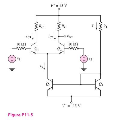
For the transistors in the circuit in Figure P11.5, the parameters are \(\beta=100\) and \(V_{B E}(\mathrm{on})=0.7 \mathrm{~V}\). The Early voltage is \(V_{A}=\infty\) for \(Q_{1}\) and \(Q_{2}\), and is \(V_{A}=50 \mathrm{~V}\) for \(Q_{3}\) and \(Q_{4}\).
(a) Design resistor values such that \(I_{3}=400 \mu \mathrm{A}\) and \(V_{C E 1}=V_{C E 2}=10 \mathrm{~V}\).
(b) Find \(A_{d}, A_{c m}\), and \(\mathrm{CMRR}_{\mathrm{dB}}\) for a one-sided output at \(v_{O 2}\).
(c) Determine the differential- and common-mode input resistances.
Fantastic news! We've Found the answer you've been seeking!
Step by Step Answer:

Answered By
Vineet Kumar Yadav
I am a biotech engineer and cleared jee exam 2 times and also i am a math tutor. topper comunity , chegg India, vedantu doubt expert( solving doubt for iit jee student on the online doubt solving app in live chat with student)
2+ Reviews
10+ Question Solved
Related Book For 

Microelectronics Circuit Analysis And Design
ISBN: 9780071289474
4th Edition
Authors: Donald A. Neamen
Question Posted:
