

The differential amplifier with the configuration shown in Figure 11.36 is to be designed to achieve a
Question:
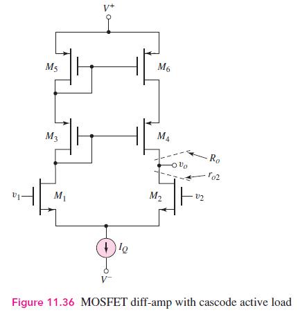
The differential amplifier with the configuration shown in Figure 11.36 is to be designed to achieve a differential-mode voltage gain of \(A_{d}=400\). The circuit parameters are to be \(V^{+}=+5 \mathrm{~V}, V^{-}=-5 \mathrm{~V}\), and \(I_{Q}=200 \mu \mathrm{A}\). The available transistors have parameters for the PMOS of \(V_{T P}=-0.5 \mathrm{~V}, k_{p}^{\prime}=40 \mu \mathrm{A} / \mathrm{V}^{2}\), and \(\lambda_{p}=0.02 \mathrm{~V}^{-1}\), and for the NMOS of \(V_{T N}=+0.5 \mathrm{~V}, k_{n}^{\prime}=80 \mu \mathrm{A} / \mathrm{V}^{2}\), and \(\lambda_{n}=0.015 \mathrm{~V}^{-1}\).
Fantastic news! We've Found the answer you've been seeking!
Step by Step Answer:

Answered By
Lisper Wanja
I am an experienced and highly motivated writer with a passion for the skills listed. I have a proven track record of my expertise and my aim is to deliver quality, well-detailed and plagiarism free projects. My genuine passion for writing combined with my ongoing professional development through school and research makes me an ideal candidate within for any assignment.
233+ Reviews
388+ Question Solved
Related Book For 

Microelectronics Circuit Analysis And Design
ISBN: 9780071289474
4th Edition
Authors: Donald A. Neamen
Question Posted:
