

Question: An all-CMOS diff-amp, including the current source circuit, with the configuration in Figure 11.32 is to be designed to have a differential-mode gain of (A_{d}=240).
An all-CMOS diff-amp, including the current source circuit, with the configuration in Figure 11.32 is to be designed to have a differential-mode gain of \(A_{d}=240\). The bias voltages are \(V^{+}=3 \mathrm{~V}\) and \(V^{-}=-3 \mathrm{~V}\). The total power dissipation in the circuit is to be limited to \(0.8 \mathrm{~mW}\). Assume the NMOS transistor parameters are \(V_{T N}=0.4 \mathrm{~V}, k_{n}^{\prime}=100 \mu \mathrm{A} / \mathrm{V}^{2}\), and \(\lambda_{n}=0.02 \mathrm{~V}^{-1}\). Assume PMOS transistor parameters of \(V_{T P}=-0.4 \mathrm{~V}\), \(k_{p}^{\prime}=40 \mu \mathrm{A} / \mathrm{V}^{2}\), and \(\lambda_{p}=0.03 \mathrm{~V}^{-1}\).
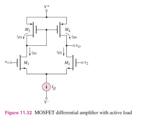
M4 M3 iD4 iD3 iD2 M M2 Figure 11.32 MOSFET differential amplifier with active load
Step by Step Solution
3.33 Rating (153 Votes )
There are 3 Steps involved in it

Get step-by-step solutions from verified subject matter experts