

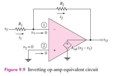
The inverting op-amp circuit in Figure 9.9 has parameters (R_{1}=20 mathrm{k} Omega), (R_{2}=200 mathrm{k} Omega), and (A_{o
Question:
The inverting op-amp circuit in Figure 9.9 has parameters \(R_{1}=20 \mathrm{k} \Omega\), \(R_{2}=200 \mathrm{k} \Omega\), and \(A_{o d}=5 \times 10^{4}\). The output voltage is \(v_{O}=-4.80 \mathrm{~V}\).
(a) Determine the closed-loop voltage gain.
(b) Find the input voltage.
(c) Determine the voltage at the inverting terminal of the op-amp.
(d) Using \(v_{I}\) from part (b), find the percent error in output voltage compared to the ideal value.
Figure 9.9:-
Fantastic news! We've Found the answer you've been seeking!
Step by Step Answer:

Answered By
Sai Krupakar Reddy
Develop and issue educational content including notes, tests, and assignments.
Supervise classes to ensure all students are learning in a safe and productive environment.
Organize supplies and resources for lectures and presentations.
Deliver personalized instruction to each student by encouraging interactive learning.
Plan and implement educational activities and events.
Ensure your classroom is clean and orderly.
Prepare and distribute periodic progress reports and semester report cards.
0 Reviews
10+ Question Solved
Related Book For 

Microelectronics Circuit Analysis And Design
ISBN: 9780071289474
4th Edition
Authors: Donald A. Neamen
Question Posted:
