

Question: The voltage regulator shown in Figure P15.79 is a variable voltage, 0 to (5 mathrm{~A}) power supply. The transistor parameters are (beta=80) and (V_{B E}(mathrm{on})=0.7
The voltage regulator shown in Figure P15.79 is a variable voltage, 0 to \(5 \mathrm{~A}\) power supply. The transistor parameters are \(\beta=80\) and \(V_{B E}(\mathrm{on})=0.7 \mathrm{~V}\). The op-amp has a finite open-loop gain of \(A_{O L}=5 \times 10^{3}\). The zero-current Zener voltage is \(V_{Z O}=5.6 \mathrm{~V}\) and the Zener resistance is \(r_{z}=12 \Omega\).
(a) For \(I_{Z}=12 \mathrm{~mA}\), find \(R_{1}\).
(b) Determine the range of output voltage as the potentiometer \(R_{3}\) is varied.
(c) If the potentiometer is set such \(x=1\), determine the load regulation. Assume \(R_{o}\) of the op-amp is zero.
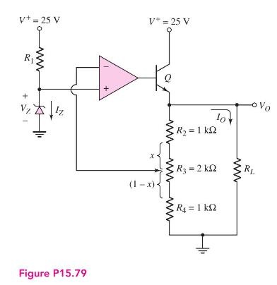
V+= 25 V V+ = 25 V R ww + Vz Figure P15.79 (1-x) R2 = 1 10 -Vo R3 = 2 k RL ww ww R = 1 kQ
Step by Step Solution
3.52 Rating (165 Votes )
There are 3 Steps involved in it

Get step-by-step solutions from verified subject matter experts