

Question: 145 The circuit in Figure 143 (b) has a low-pass transfer function given in Eq. (146) and repeated below In Section 142, we developed equal-element
14–5 The circuit in Figure 14–3
(b) has a low-pass transfer function given in Eq. (14–6) and repeated below
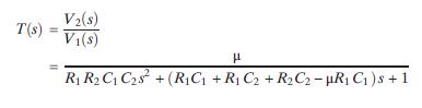
In Section 14–2, we developed equal-element and unity-gain design methods for this circuit. This problem explores an equal-time constant design method. Using R1C1 =R2C2 and μ = 2, develop a method of selecting values for C1, C2, R1, and R2. Then select values so that the filter has a cutoff frequency of 2 krad/s and a ζ of 0.05. Use MATLAB to plot the filter’s Bode diagram. Determine the location in rad/s and magnitude in dB of the peak in the frequency response.
V2(s) T(s) = V(s) R R2 C C28 +(RC +R C2 + R2C2-R C)s +1
Step by Step Solution
There are 3 Steps involved in it

Get step-by-step solutions from verified subject matter experts