

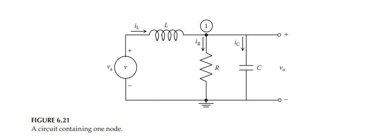
A simple low-pass filter can be realized by an RLC circuit (see Figure 6.21 in Example 6.4),
Question:
A simple low-pass filter can be realized by an RLC circuit (see Figure 6.21 in Example 6.4), which passes signals with frequencies lower than a certain cutoff frequency and attenuates signals with a frequency higher than the cutoff frequency. Assume that the parameter values are \(R=500 \Omega, L=100 \mathrm{mH}\), and \(C=10 \mu \mathrm{F}\).
The circuit is connected to an AC voltage source, which has an amplitude of \(1 \mathrm{~V}\) and a varying frequency.
a. Build a Simscape model of the physical system and find the output voltage \(v_{\mathrm{o}}(t)\) when the frequency of the input voltage is 500, 1000, and \(2500 \mathrm{rad} / \mathrm{s}\).
b. Build a Simulink model of the system based on the transfer function \(V_{\mathrm{o}}(s) / V_{\mathrm{a}}(s)\), and verify the results obtained in Part (a).
Step by Step Answer:


Modeling And Analysis Of Dynamic Systems
ISBN: 9781138726420
3rd Edition
Authors: Ramin S. Esfandiari, Bei Lu
