

Question: A Consider the parallel RLC circuit shown in Example 6.2, in which (R=2 Omega), (L=1 mathrm{H}), and (C=0.5 mathrm{~F}). The circuit is driven by a
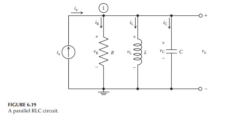
A Consider the parallel RLC circuit shown in Example 6.2, in which \(R=2 \Omega\), \(L=1 \mathrm{H}\), and \(C=0.5 \mathrm{~F}\). The circuit is driven by a controlled current source \(i_{\mathrm{a}}(\mathrm{t})=10 u(t)\), where \(u(t)\) is a unit-step function.
Circuit From Example 6.2:
a. Build a Simscape model of the physical system and find the voltage across the capacitor \(v_{\mathrm{C}}(t)\) and the current through the inductor \(i_{\mathrm{L}}(t)\).
b. Refer to the results obtained in Example 6.2. Build a Simulink model of the system based on the transfer function \(V_{\mathrm{C}}(s) / I_{\mathrm{a}}(s)\) and find the voltage across the capacitor \(v_{\mathrm{C}}(t)\).
c. Refer to the results obtained in Example 6.2. Build a Simulink model of the system based on the transfer function \(I_{\mathrm{L}}(s) / I_{\mathrm{a}}(s)\) and find the current through the inductor \(i_{\mathrm{L}}(t)\).
FIGURE 6.19 A parallel RLC circuit. VR ia R VL elle + L VC C Vo
Step by Step Solution
3.47 Rating (167 Votes )
There are 3 Steps involved in it

Get step-by-step solutions from verified subject matter experts