

Question: Bandpass to Bandstop Transformation The three-terminal circuit in Figure P1462 (a) has a bandpass transfer function of the form Ts VOs VSs 2zs=v0
Bandpass to Bandstop Transformation The three-terminal circuit in Figure P14–62
(a) has a bandpass transfer function of the form TðsÞ ¼ VOðsÞ
VSðsÞ
¼ 2zðs=v0Þ
ðs=v0Þ2 þ 2zðs=v0Þ þ 1 Show that the circuit in Figure P14–62
(b) has a bandstop transfer function of the form TðsÞ ¼ VOðsÞ
VSðsÞ
¼
ðs=v0Þ2 þ 1
ðs=v0Þ2 þ 2zðs=v0Þ þ 1 That is, show that interchanging the input and ground terminals changes a unity-gain bandpass circuit into a unity-gain bandstop circuit.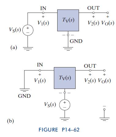
Vs(s) (a) GND IN + Ty(s) V(s) IN GND OUT + V2(s) Vo(s) OUT + + + V(s) Tv(s) V(s) Vo(s) + Vs(s) (b) FIGURE P14-62
Step by Step Solution
There are 3 Steps involved in it
1 Expert Approved Answer
Step: 1 Unlock

Question Has Been Solved by an Expert!
Get step-by-step solutions from verified subject matter experts
Step: 2 Unlock
Step: 3 Unlock