

Consider the electrical circuit shown in Figure 7.19, where the input (mathbf{u}(mathbf{t})) is a current and the
Question:
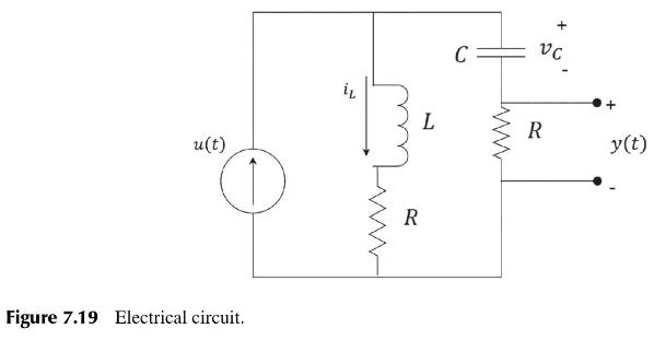
Consider the electrical circuit shown in Figure 7.19, where the input \(\mathbf{u}(\mathbf{t})\) is a current and the output \(\mathbf{y}(\mathbf{t})\) is a voltage.
(a) Explain why the state variables should be chosen as \(x_{1}=i_{L}\) and \(x_{2}=v_{C}\).
(b) Write down state-variable equations for the system, and deduce the system's State-Space model \((A, B, C, D)\).
(c) Explain the concepts of controllability and observability. How are these properties determined for a system whose model is given by matrices \((A, B, C, D)\) ?
(d) In Figure 7.19, what conditions on R, \(L\), and \(C\) will guarantee that the system is: (i) controllable? (ii) observable?
(e) For the State-Space model derived in (b), if \(R=1\) Ohms; \(L=1 \mathrm{H}\) and \(\mathrm{C}=1 \mathrm{~F}\) :
(i) Determine the controllability and observability of the system.
(ii) Derive the circuit's Transfer Function model using matrix algebra.
(iii) What is the significance of the pole-zero cancellation in the derivation of the Transfer Function model?
(iv) Derive the circuit's Transfer Function model using the state-variable equations of the system which are obtained by working backwards from the State-Space model (A, B, \(C, D)\). Why is this result the same as that obtained in (ii)?
(v) Design a block diagram for the circuit with one integrator for each state variable.
Step by Step Answer:


Design And Analysis Of Control Systems Driving The Fourth Industrial Revolution
ISBN: 9781032718804
2nd Edition
Authors: Arthur G O Mutambara
