

Question: Consider the feedback control system shown in Figure 10.44a. a. If the desired closed-loop poles are located within the shaded regions shown in Figure 10.44b,
Consider the feedback control system shown in Figure 10.44a.
a. If the desired closed-loop poles are located within the shaded regions shown in Figure 10.44b, determine the corresponding ranges of ωn and ζ of the closedloop system.
b. Design a PI controller such that the closed-loop poles are at p1,2=−9±12j.
c. Compute the steady-state errors of the plant and the closed-loop system to a unit-step reference input.
d. Verify the results in Part (c) using MATLAB by plotting the unit-step responses of the plant and the closed-loop system.
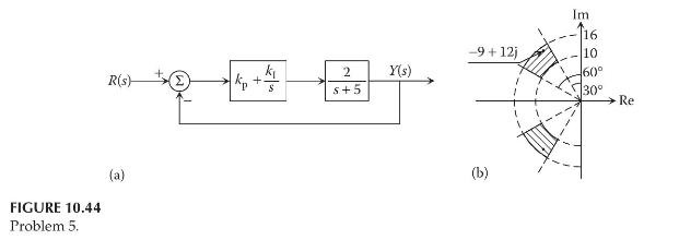
FIGURE 10.44 Problem 5. Im 16 -9+12j 10 R(s) kp k 2 Y(s) 60 + S S+5 30 Re (a) (b)
Step by Step Solution
3.28 Rating (151 Votes )
There are 3 Steps involved in it

Get step-by-step solutions from verified subject matter experts