

Consider the RL circuit shown in Figure 6.25, in which (R=35 Omega) and (L=10 mathrm{H}). When the
Question:
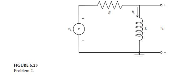
Consider the RL circuit shown in Figure 6.25, in which \(R=35 \Omega\) and \(L=10 \mathrm{H}\). When the switch is closed at 0 seconds, the circuit is driven by a 6 V DC voltage source. Assume that all initial conditions are zero.
a. Build a Simscape model of the physical system and find the loop current \(i_{\mathrm{L}}(t)\) and the voltage across the inductor \(v_{\mathrm{L}}(t)\).
b. Build a Simulink model of the system based on the differential equation relating \(i_{\mathrm{L}}\) and \(v_{\mathrm{a}}\), and find the loop current \(i_{\mathrm{L}}(t)\).
c. Build a Simulink model of the system based on the transfer function \(V_{\mathrm{L}}(s) / V_{\mathrm{a}}(s)\), and find the voltage across the inductor \(v_{\mathrm{L}}(t)\).
Step by Step Answer:


Modeling And Analysis Of Dynamic Systems
ISBN: 9781138726420
3rd Edition
Authors: Ramin S. Esfandiari, Bei Lu
