

Question: For the mechanical system shown in Fig. P 3. 25, the input and output are the displacement $x$ and $y$ respectively. The input is a
For the mechanical system shown in Fig. P 3. 25, the input and output are the displacement $x$ and $y$ respectively. The input is a step displacement of $0.4 \mathrm{~m}$. Assuming the system remains linear throughout the transient period and $m=3 \mathrm{~kg}, c=3 \mathrm{~N}-\mathrm{s} / \mathrm{m}$, and $k=1 \mathrm{~N} / \mathrm{m}$, determine the response of the system using MATLAB.
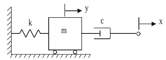
Fig. P 3. 25
m y C X
Step by Step Solution
There are 3 Steps involved in it
1 Expert Approved Answer
Step: 1 Unlock

Question Has Been Solved by an Expert!
Get step-by-step solutions from verified subject matter experts
Step: 2 Unlock
Step: 3 Unlock