

Question: Re-work Example 14.3 with (mathrm{R}_{text {Load }}=40 Omega) /phase, (mathrm{X}_{text {Load }}=60 Omega /) phase, and (mathrm{X}_{mathrm{C}}=) (60 Omega /) phase. Data From Example 14.3:-
Re-work Example 14.3 with \(\mathrm{R}_{\text {Load }}=40 \Omega\) /phase, \(\mathrm{X}_{\text {Load }}=60 \Omega /\) phase, and \(\mathrm{X}_{\mathrm{C}}=\) \(60 \Omega /\) phase.
Data From Example 14.3:-
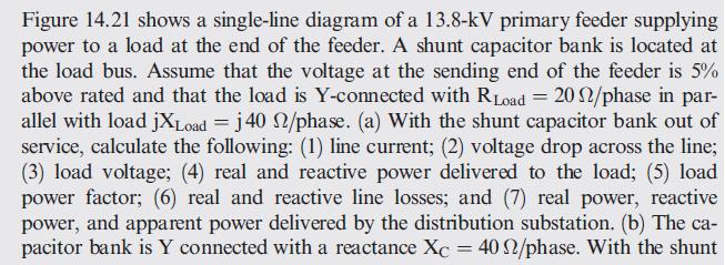
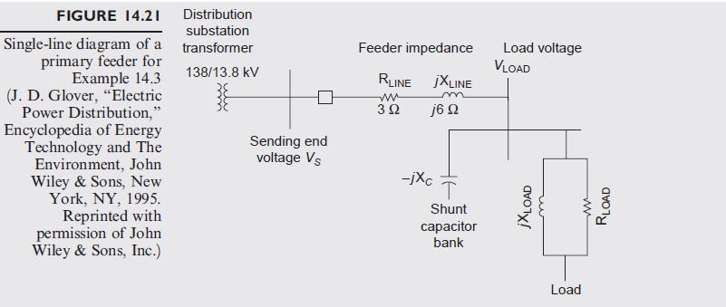

Figure 14.21 shows a single-line diagram of a 13.8-kV primary feeder supplying power to a load at the end of the feeder. A shunt capacitor bank is located at the load bus. Assume that the voltage at the sending end of the feeder is 5% above rated and that the load is Y-connected with R Load = 20 2/phase in par- allel with load jXLoad = j 40 2/phase. (a) With the shunt capacitor bank out of service, calculate the following: (1) line current; (2) voltage drop across the line; (3) load voltage; (4) real and reactive power delivered to the load; (5) load power factor; (6) real and reactive line losses; and (7) real power, reactive power, and apparent power delivered by the distribution substation. (b) The ca- pacitor bank is Y connected with a reactance Xc = 40 2/phase. With the shunt
Step by Step Solution
3.54 Rating (151 Votes )
There are 3 Steps involved in it

Get step-by-step solutions from verified subject matter experts