

Question: The active filter in Figure P146 has a transfer function of the form Ts V2s V1s R2=R1 R2R3C1C2s2 R3C2 R2C21
The active filter in Figure P14–6 has a transfer function of the form TðsÞ ¼ V2ðsÞ
V1ðsÞ
¼
R2=R1 R2R3C1C2s2 þ R3C2 þ R2C2ð1 þ R3=R1½ Þs þ 1 Using R1¼R2¼R3¼R, develop a method of selecting values for C1, C2 and R. Then select values so that the filter has a cutoff frequency of 150 krad/s and a z of 0.01. Use MATLAB to plot the filter’s Bode diagram. Build and simulate your circuit in OrCAD and compare the results with MATLAB’s.
Determine the location in rad/s and magnitude in dB of the peak in the frequency response.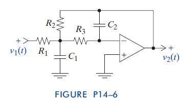
+W v1(t) R R R3 C2 ww >+ C + v2(t) FIGURE P14-6
Step by Step Solution
There are 3 Steps involved in it
1 Expert Approved Answer
Step: 1 Unlock

Question Has Been Solved by an Expert!
Get step-by-step solutions from verified subject matter experts
Step: 2 Unlock
Step: 3 Unlock