

Question: With the circuit in the zero state, the input to the integrator shown in Figure P1061 is v1(t) cos1000t V. The desired output is
With the circuit in the zero state, the input to the integrator shown in Figure P10–61 is v1(t) ¼ cos1000t V.
The desired output is v2(t) ¼ sin 1000t V. Use Laplace to select values of R and C to produce the desired output. If the capacitor had 10 V across it at t ¼ 0, how would that affect the output?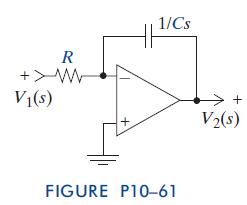
R +W 1/Cs V(s) FIGURE P10-61 > + V2(s)
Step by Step Solution
★★★★★
3.48 Rating (151 Votes )
There are 3 Steps involved in it
1 Expert Approved Answer
Step: 1 Unlock

Question Has Been Solved by an Expert!
Get step-by-step solutions from verified subject matter experts
Step: 2 Unlock
Step: 3 Unlock