

A CO-8 relay with a current tap setting of 5 amperes is used with the 100:5 CT
Question:
A CO-8 relay with a current tap setting of 5 amperes is used with the 100:5 CT in Example 10.1. The CT secondary current I' is the input to the relay operating coil. The CO-8 relay burden is shown in the following table for various relay input currents.
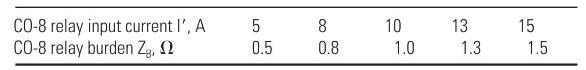
Primary current and CT error are computed in Example 10.1 for the 5-, 8-, and \(15-\mathrm{A}\) relay input currents. Compute the primary current and \(\mathrm{CT}\) error for
(a) \(\mathrm{I}^{\prime}=10 \mathrm{~A}\) and \(\mathrm{Z}_{\mathrm{B}}=1.0 \Omega\), and for
(b) \(\mathrm{I}^{\prime}=13 \mathrm{~A}\) and \(\mathrm{Z}_{\mathrm{B}}=1.3 \Omega\).
(c) Plot I' versus I for the above five values of I'.
(d) For reliable relay operation, the fault-to-pickup current ratio with minimum fault current should be greater than two. Determine the minimum fault current for application of this CT and relay with 5-A tap setting.
Example 10.1
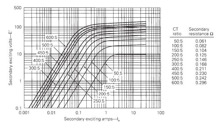
Evaluate the performance of the multiratio CT in Figure 10.8 with a 100:5 CT ratio, for the following secondary output currents and burdens:
(a) \(\mathrm{I}^{\prime}=5 \mathrm{~A}\) and \(\mathrm{Z}_{\mathrm{B}}=0.5 \Omega\);
(b) \(\mathrm{I}^{\prime}=8 \mathrm{~A}\) and \(\mathrm{Z}_{\mathrm{B}}=0.8 \Omega\); and
(c) \(\mathrm{I}^{\prime}=15 \mathrm{~A}\) and \(\mathrm{Z}_{\mathrm{B}}=1.5 \Omega\). Also, compute the \(\mathrm{CT}\) error for each output current.
Figure 10.8
Step by Step Answer:

This question has not been answered yet.
You can Ask your question!


Power System Analysis And Design
ISBN: 9781305632134
6th Edition
Authors: J. Duncan Glover, Thomas Overbye, Mulukutla S. Sarma
