

Question: (a) Consider a medium-length transmission line represented by a nominal (pi) circuit shown in Figure 5.3 of the text. Draw a phasor diagram for lagging
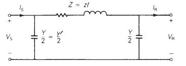
(a) Consider a medium-length transmission line represented by a nominal \(\pi\) circuit shown in Figure 5.3 of the text. Draw a phasor diagram for lagging power-factor condition at the load (receiving end).
(b) Now consider a nominal \(\mathrm{T}\) circuit of the medium-length transmission line shown in Figure 5.18.
First draw the corresponding phasor diagram for lagging power-factor load condition.
Then determine the \(A B C D\) parameters in terms of \(Y\) and \(Z\) for the nominal \(\mathrm{T}\) circuit and for the nominal \(\pi\) circuit of part (a).
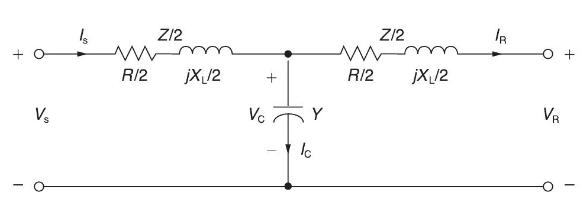
Figure 5.3
+ V Z/2 www R/2 jX 12 Vc + Y Ic Z/2 www R/2 jX /2 IR VR +
Step by Step Solution
3.48 Rating (155 Votes )
There are 3 Steps involved in it

Get step-by-step solutions from verified subject matter experts