

Question: A1- (mu mathrm{F}) capacitor and a 100-mH inductor are connected in parallel with a closed switch as shown in Figure P6-14. The inductor has (-10
A1- \(\mu \mathrm{F}\) capacitor and a 100-mH inductor are connected in parallel with a closed switch as shown in Figure P6-14. The inductor has \(-10 \mathrm{~mA}\) flowing through it at \(t=0\). The switch opens at \(t=0\).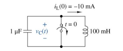
(a) Find the initial voltage across the capacitor at \(t=0\).
(b) Write an equation for the voltage across the elements for \(t>0\). Do not solve it.
(c) Simulate the circuit using Multisim. Connect an inductor in parallel with a capacitor and assign the appropriate initial conditions and run a transient analysis. Plot the voltage across the elements for \(4 \mathrm{~ms}\).
(d) Characterize the response signal.
(e) Now add a 1-k \(\Omega\) resistor in parallel to the inductor and capacitor. Run the simulation with the resistor. Recalling the signals studied in Chapter 5 , what does the response of \(v_{\mathrm{C}}(t)\) look like?
(f) Explain what happened in terms of the energy stored in the circuit.
1 F: + vc(1) iL(0) = -10 mA 1=0 100 mH
Step by Step Solution
3.56 Rating (146 Votes )
There are 3 Steps involved in it
a b c d e f The voltage across the capac... View full answer

Get step-by-step solutions from verified subject matter experts