

Question: As shown in Figure 13.34, an ideal current source consisting of a 10-kA pulse with (50-mu) s duration is applied to the junction of a
As shown in Figure 13.34, an ideal current source consisting of a 10-kA pulse with \(50-\mu\) s duration is applied to the junction of a single-phase, lossless cable and a single-phase, lossless overhead line. The cable has a \(200-\Omega\) characteristic impedance, \(2 \times 10^{8} \mathrm{~m} / \mathrm{s}\) velocity of propagation, and \(20-\mathrm{km}\) length. The overhead line has a \(300-\Omega\) characteristic impedance, \(3 \times 10^{8} \mathrm{~m} / \mathrm{s}\) velocity of propagation, and \(60-\mathrm{km}\) length. The sending end of the cable is terminated by a \(400-\Omega\) resistor, and the receiving end of the overhead line is terminated by a \(100-\Omega\) resistor. Both the line and cable are initially unenergized.
(a) Determine the voltage reflection coefficients \(\Gamma_{\mathrm{S}}, \Gamma_{\mathrm{R}}, \Gamma_{\mathrm{AA}}, \Gamma_{\mathrm{AB}}, \Gamma_{\mathrm{BA}}\), and \(\Gamma_{\mathrm{BB}}\)
(b) Draw the Bewley lattice diagram for \(0 \leq t \leq 0.8 \mathrm{~ms}\).
(c) Determine and plot the voltage \(v(0, t)\) at \(x=\) 0 versus time \(t\) for \(0 \leq t \leq 0.8 \mathrm{~ms}\).
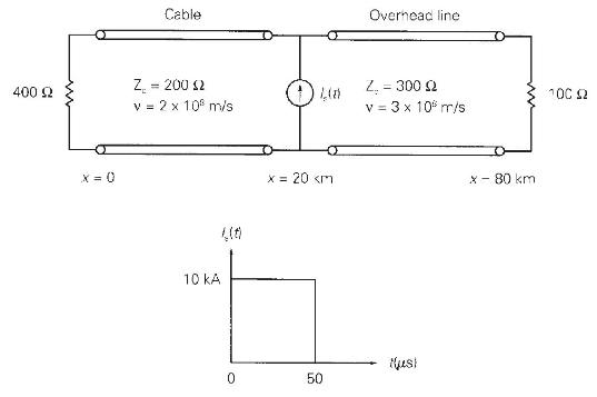
400 2 X=0 Cable Z = 200 12 v = 2 x 10 m/s 10 KA O x = 20
Step by Step Solution
3.40 Rating (163 Votes )
There are 3 Steps involved in it

Get step-by-step solutions from verified subject matter experts