

Question: At t = 0 t = 0 , the switch in Figure P6-51 is closed and thereafter the voltage across the capacitor is v C
At t=0, the switch in Figure P6-51 is closed and thereafter the voltage across the capacitor is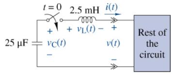 vC(t)=(10+10,000t)e−8000t V
Use MATLAB to solve all of the following problems.
(a) Use the capacitor's i−v characteristic to find the current i(t) for t≥0.
(b) Use the inductor's i−v characteristic and i(t) to find v L(t) for t≥0.
(c) Use vC(t),vL(t), and KVL to find the voltage v(t) delivered to the rest of the circuit.
(d) The v(t) found in (c) should be proportional to the i ( t ) found in (a). If so, what is the equivalent resistance looking into the rest of the circuit?
(e) On the same axes, plot vC(t),vL(t), and v(t). Use a different color for each waveform. Use the plots to verify KVL for the circuit.
25 F t=0 2.5 mH i(t) Xo voo - + VL (1)- + vc(1) v(t) VI Rest of the circuit
Step by Step Solution
3.36 Rating (146 Votes )
There are 3 Steps involved in it
a b c d e Apply the equation for the current through a c... View full answer

Get step-by-step solutions from verified subject matter experts