

Question: Consider a single-phase electric system shown in Figure 3.33. Transformers are rated as follows: X-Y 15 MVA, 13.8/138 kV, leakage reactance 10% Y-Z 15 MVA,
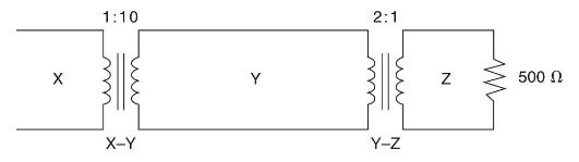
Consider a single-phase electric system shown in Figure 3.33. Transformers are rated as follows:
X-Y 15 MVA, 13.8/138 kV, leakage reactance 10\%
Y-Z 15 MVA, 138/69 kV, leakage reactance 8\%
With the base in circuit Y chosen as \(15 \mathrm{MVA}, 138 \mathrm{kV}\), determine the perunit impedance of the \(500 \Omega\) resistive load in circuit \(Z\), referred to circuits Z, Y, and X. Neglecting magnetizing currents, transformer resistances, and line impedances, draw the impedance diagram in per unit.
X 1:10 X-Y Y 2:1 Y-Z N 500
Step by Step Solution
★★★★★
3.42 Rating (152 Votes )
There are 3 Steps involved in it
1 Expert Approved Answer
Step: 1 Unlock

Question Has Been Solved by an Expert!
Get step-by-step solutions from verified subject matter experts
Step: 2 Unlock
Step: 3 Unlock