

Draw the zero-sequence reactance diagram for the power system shown in Figure 3.33. The zero-sequence reactance of
Question:
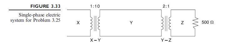
Draw the zero-sequence reactance diagram for the power system shown in Figure 3.33. The zero-sequence reactance of each generator and of the synchronous motor is 0.05 per unit based on equipment ratings. Generator 2 is grounded through a neutral reactor of 0.06 per unit on a \(100-\mathrm{MVA}, 18-\mathrm{kV}\) base. The zero-sequence reactance of each transmission line is assumed to be three times its positive-sequence reactance. Use the same base as in Problem 3.29.
Data From Figure 3.33:-
Data From Problem 3.29:-
A completely transposed three-phase transmission line of \(200 \mathrm{~km}\) in length has the following symmetrical sequence impedances and sequence admittances:
\[
\begin{aligned}
& Z_{1}=Z_{2}=j 0.5 \Omega / \mathrm{km} ; \quad Z_{0}=j 2 \Omega / \mathrm{km} \\
& Y_{1}=Y_{2}=j 3 \times 10^{-9} \mathrm{~s} / \mathrm{m} ; \quad Y_{0}=j 1 \times 10^{-9} \mathrm{~s} / \mathrm{m}
\end{aligned}
\]
Set up the nominal \(\Pi\) sequence circuits of this medium-length line.
Step by Step Answer:

This question has not been answered yet.
You can Ask your question!

Power System Analysis And Design
ISBN: 9781111425777
5th Edition
Authors: J Duncan Glover, Mulukutla S Sarma, Thomas Overbye
