

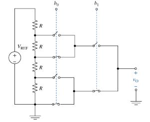
Question: Figure P2-70 shows a programmable voltage divider in which digital inputs (b_{0}) and (b_{1}) control complementary analog switches connecting a multitap voltage divider to the
Figure P2-70 shows a programmable voltage divider in which digital inputs \(b_{0}\) and \(b_{1}\) control complementary analog switches connecting a multitap voltage divider to the analog output \(v_{\mathrm{O}}\). The switch positions in the figure apply when digital inputs are low. When inputs go high the switch positions reverse. Find the analog output voltage for \(\left(b_{1}, b_{0}ight)=(0,0),(0,1),(1,0)\), and \((1,1)\) when \(V_{\mathrm{REF}}=12 \mathrm{~V}\).
VRFF R www R R +6 9+11
Step by Step Solution
3.21 Rating (156 Votes )
There are 3 Steps involved in it
There are four equal resistors in series with a voltage source so each drops one quar... View full answer

Get step-by-step solutions from verified subject matter experts