

Figure P2-71 (a) shows a voltmeter circuit consisting of a D'Arsonval meter, two series resistors, and a
Question:
Figure P2-71 (a) shows a voltmeter circuit consisting of a D'Arsonval meter, two series resistors, and a two-position selector switch. A current of \(I_{\mathrm{FS}}=400 \mu \mathrm{A}\) produces full-scale deflection of the D'Arsonval meter, whose internal resistance is \(R_{\mathrm{M}}=25 \Omega\).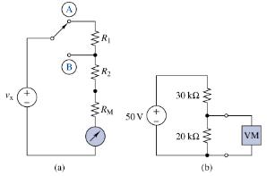 (a) Select the series resistance \(R_{1}\) and \(R_{2}\) so that a voltage \(v_{\mathrm{x}}=100 \mathrm{~V}\) produces full-scale deflection when the switch is in position A, and voltage \(v_{\mathrm{x}}=10 \mathrm{~V}\) produces fullscale deflection when the switch is in position \(\mathrm{B}\).
(b) image What is the voltage across the \(20-\mathrm{k} \Omega\) resistor in Figure P2-71 (b)? What is the voltage when the voltmeter in part (a) is set to position A and connected across the \(20-\mathrm{k} \Omega\) resistor? What is the percentage error introduced connecting the voltmeter?
(c) image A different D'Arsonval meter is available with an internal resistance of \(100 \Omega\) and a full-scale deflection current of \(100 \mu \mathrm{A}\). If the voltmeter in part (a) is redesigned using this D'Arsonval meter, would the error found in part (b) be smaller or larger? Explain.
Step by Step Answer:
a b c First solve for R such that a 10V input at position B ca...View the full answer


The Analysis And Design Of Linear Circuits
ISBN: 9781119913023
10th Edition
Authors: Roland E. Thomas, Albert J. Rosa, Gregory J. Toussaint
