

Question: For the power system given in Problem 7.12, a three-phase short circuit occurs at bus 2, where the prefault voltage is (525 mathrm{kV}). Prefault load
For the power system given in Problem 7.12, a three-phase short circuit occurs at bus 2, where the prefault voltage is \(525 \mathrm{kV}\). Prefault load current is neglected. Determine the
(a) Thévenin equivalent at the fault,
(b) subtransient fault current in per unit and in kA rms, and
(c) contributions to the fault from lines \(1-2,2-3\), and \(2-4\).
Problem 7.12
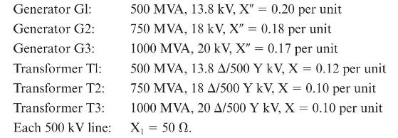
Equipment ratings for the four-bus power system shown in Figure 7.14 are as follows:
A three-phase short circuit occurs at bus 1, where the prefault voltage is \(525 \mathrm{kV}\). Prefault load current is neglected. Draw the positive-sequence reactance diagram in per unit on a \(1000-\mathrm{MVA}, 20-\mathrm{kV}\) base in the zone of generator G3.
Generator Gl: Generator G2: Generator G3: Transformer Tl: Transformer T2: Transformer T3: Each 500 kV line: 500 MVA, 13.8 kV, X"= 0.20 per unit 750 MVA, 18 kV, X" = 0.18 per unit 1000 MVA, 20 kV, X" = 0.17 per unit 500 MVA, 13.8 A/500 Y kV, X = 0.12 per unit 750 MVA, 18 A/500 Y kV, X = 0.10 per unit 1000 MVA, 20 A/500 Y kV, X = 0.10 per unit X 50 . =
Step by Step Solution
3.45 Rating (148 Votes )
There are 3 Steps involved in it

Get step-by-step solutions from verified subject matter experts