

In the circuit of Figure 7.1, let (mathrm{R}=0.125 Omega ., mathrm{L}=10 mathrm{mH}), and the source voltage is
Question:
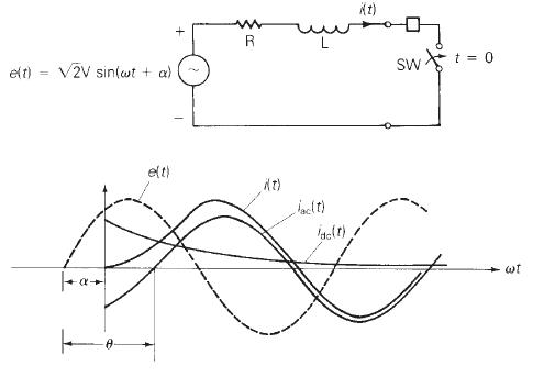
In the circuit of Figure 7.1, let \(\mathrm{R}=0.125 \Omega ., \mathrm{L}=10 \mathrm{mH}\), and the source voltage is \(e(\mathrm{t})=151 \sin (377 \mathrm{t}+\alpha) \mathrm{V}\). Determine the current response after closing the switch for the following cases:
(a) no dc offset or
(b) maximum dc offset. Sketch the current waveform up to \(t=0.10 \mathrm{~s}\) corresponding to parts (a) and (b).
Figure 7.1
Step by Step Answer:

This question has not been answered yet.
You can Ask your question!
Related Book For 

Power System Analysis And Design
ISBN: 9781305632134
6th Edition
Authors: J. Duncan Glover, Thomas Overbye, Mulukutla S. Sarma
Question Posted:
