

Question: Rework Problem 13.3 if (Z_{mathrm{R}}=Z_{c}) at the receiving end and the source voltage at the sending end is (e_{mathrm{G}}(t)=mathrm{E} u_{-1}(t)), with an inductive source impedance
Rework Problem 13.3 if \(Z_{\mathrm{R}}=Z_{c}\) at the receiving end and the source voltage at the sending end is \(e_{\mathrm{G}}(t)=\mathrm{E} u_{-1}(t)\), with an inductive source impedance \(\mathrm{Z}_{\mathrm{G}}(s)=s 2 \mathrm{~L}_{\mathrm{G}}\). Both the line and source inductor are initially unenergized.
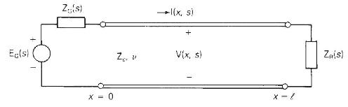
Problem 13.3
Referring to the single-phase two-wire lossless line shown in Figure 13.3, the receiving end is terminated by an inductor with \(2 \mathrm{~L}_{\mathrm{R}}\) henries. The source voltage at the sending end is a step, \(e_{\mathrm{G}}(t)=\mathrm{E} u_{-1}(t)\) with \(\mathrm{Z}_{\mathrm{G}}=Z_{c}\). Both the line and inductor are initially unenergized. Determine and plot the voltage at the center of the line \(v(l / 2, t)\) versus time \(t\).
Figure 13.3
Ec(s) Z(s) X = 0 2/ l(x, s) + V(x, s) x = 1 Za(s)
Step by Step Solution
3.50 Rating (153 Votes )
There are 3 Steps involved in it

Get step-by-step solutions from verified subject matter experts