

Question: The block-diagram representation of a closed-loop automatic regulating system, in which generator voltage control is accomplished by controlling the exciter voltage, is shown in Figure
The block-diagram representation of a closed-loop automatic regulating system, in which generator voltage control is accomplished by controlling the exciter voltage, is shown in Figure 12.14. \(\mathrm{T}_{\mathrm{a}}, \mathrm{T}_{\mathrm{e}}\), and \(\mathrm{T}_{\mathrm{f}}\) are the time constants associated with the amplifier, exciter, and generator field circuit, respectively.
(a) Find the open-loop transfer function G(s).
(b) Evaluate the minimum open-loop gain such that the steady-state error \(\Delta \mathrm{e}_{\mathrm{ss}}\) does not exceed \(1 \%\).
(c) Discuss the nature of the dynamic response of the system to a step change in the reference input voltage.
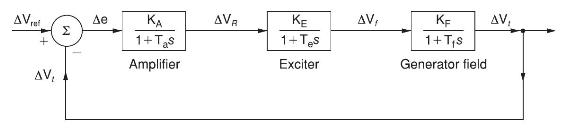
AV + AV, KA 1+ Tas Amplifier AVA KE 1+Ts Exciter AV, KF 1+ TS Generator field AV
Step by Step Solution
3.53 Rating (153 Votes )
There are 3 Steps involved in it

Get step-by-step solutions from verified subject matter experts