

The circuit in Figure P4=76 is a four-bit DAC. The DAC output is the voltage (v_{mathrm{O}}) and
Question:
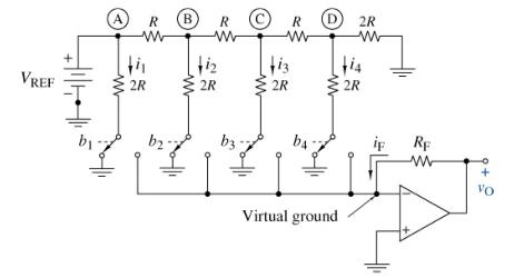
The circuit in Figure P4=76 is a four-bit DAC. The DAC output is the voltage \(v_{\mathrm{O}}\) and the input is the binary code represented by bits \(b_{1}, b_{2}, b_{3}\), and \(b_{4}\). The input bits are either \(\mathrm{o}\) (low) or 1 (high), and each controls one of the four switches in the figure. When bits are low, their switches are in the left position, directing the \(2 R\) leg currents to ground. When bits are high, their switches move to the right position, directing the \(2 R\) leg currents to the OP AMP's inverting input. The 2R leg currents do not change when switching from left to right because the inverting input is a virtual ground \(\left(v_{\mathrm{N}}=v_{\mathrm{P}}=0ight)\). The purpose of this problem is to show that this constant-current switching produces the following input-output relationship.
\[
v_{\mathrm{O}}=-\frac{R_{\mathrm{F}}}{2 R} V_{\mathrm{REF}}\left(b_{1}+\frac{b_{2}}{2}+\frac{b_{3}}{4}+\frac{b_{4}}{8}ight)
\]
(a) Since the inverting input is a virtual ground, show that the currents in the \(2 R\) legs are \(i_{1}=V_{\mathrm{REF}} / 2 R, i_{2}=V_{\mathrm{REF}}\) \(/ 4 R, i_{3}=V_{\mathrm{REF}} / 8 R\), and \(i_{4}=V_{\mathrm{REF}} / 16 R\), regardless of switch positions.
(b) Show that the sum of currents at the inverting input is \[
b_{1} i_{1}+b_{2} i_{2}+b_{3} i_{3}+b_{4} i_{4}+i_{\mathrm{F}}=0
\]
where bits \(b_{\mathrm{k}}(k=1,2,3,4)\) are either \(\mathrm{o}\) or 1 .
(c) Use the results in parts (a) and (b) to show that the OP AMP output voltage is as stated above.
Step by Step Answer:
a b c The equivalent resistance seen by the reference voltage source is R so the current flow...View the full answer


The Analysis And Design Of Linear Circuits
ISBN: 9781119913023
10th Edition
Authors: Roland E. Thomas, Albert J. Rosa, Gregory J. Toussaint
