

The circuit in Figure P7-13 contains two energy storage devices connected to a battery via a single-pole,
Question:
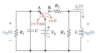
The circuit in Figure P7-13 contains two energy storage devices connected to a battery via a single-pole, doublethrow switch (SPDT). The switch has been in position A for a long time. At \(t=0\), the switch moves to position B. After \(5 \mathrm{~ms}\), it moves back to position A. If \(R_{1}=2 \mathrm{k} \Omega, C=0.5 \mu \mathrm{F}, V_{\mathrm{S}}=15 \mathrm{~V}, R\) \({ }_{2}=R_{3}=100 \Omega\), and \(L=100 \mathrm{mH}\), plot \(v_{01}(t)\) and \(v_{02}(t)\) from \(t=0\) to \(t=10 \mathrm{~ms}\).
Fantastic news! We've Found the answer you've been seeking!
Step by Step Answer:

Answered By
Fahmin Arakkal
Tutoring and Contributing expert question and answers to teachers and students.
Primarily oversees the Heat and Mass Transfer contents presented on websites and blogs.
Responsible for Creating, Editing, Updating all contents related Chemical Engineering in
latex language
8+ Reviews
22+ Question Solved
Related Book For 

The Analysis And Design Of Linear Circuits
ISBN: 9781119913023
10th Edition
Authors: Roland E. Thomas, Albert J. Rosa, Gregory J. Toussaint
Question Posted:
