

For the circuit in Figure P7-13, the switch has been in position (mathrm{B}) a long time. At
Question:
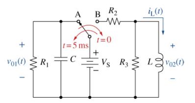
For the circuit in Figure P7-13, the switch has been in position \(\mathrm{B}\) a long time. At \(t=0\), the switch moves to position \(\mathrm{A}\). After \(5 \mathrm{~ms}\), it moves back to position B. If \(R_{1}=1 \mathrm{k} \Omega, C=1 \mu \mathrm{F}, V\) \(\mathrm{S}=10 \mathrm{~V}, R_{2}=R_{3}=100 \Omega\), and \(L=100 \mathrm{mH}\), using Multisim plot \(i_{\mathrm{L}}(t)\) from \(t=5 \mathrm{~ms}\) to \(t=10 \mathrm{~ms}\).
Fantastic news! We've Found the answer you've been seeking!
Step by Step Answer:

Answered By
Sandip Nandnawar
I am a B.E (Information technology) from GECA and also have an M.C.M from The University of RTMNU, MH.
I worked as a software developer (Programmer and TL). Also working as an expert for the last 6 years and deal with complex assessment and projects. I have a team and lead a team of experts and conducted primary and secondary research. I am a senior software engg and senior expert and deal with all types of CSE and IT and other IT-related assessments and projects and homework.
1+ Reviews
10+ Question Solved
Related Book For 

The Analysis And Design Of Linear Circuits
ISBN: 9781119913023
10th Edition
Authors: Roland E. Thomas, Albert J. Rosa, Gregory J. Toussaint
Question Posted:
